N723-EA Hardware User Guide
Chapter 5 Application Interfaces
Copyright © Neoway Technology Co., Ltd. All rights reserved.
1.8 V/3.0 V (self-adaptive)
USIM data input and
output
Connecting a 4.7 kΩ pull-up
resistor to USIM_VCC is
required.
Leave this pin floating if it is not
used.
Leave this pin floating if it is not
used.
Connecting this pin to
VDD_1P8 through a 47 kΩ
pull-up resistor is required.
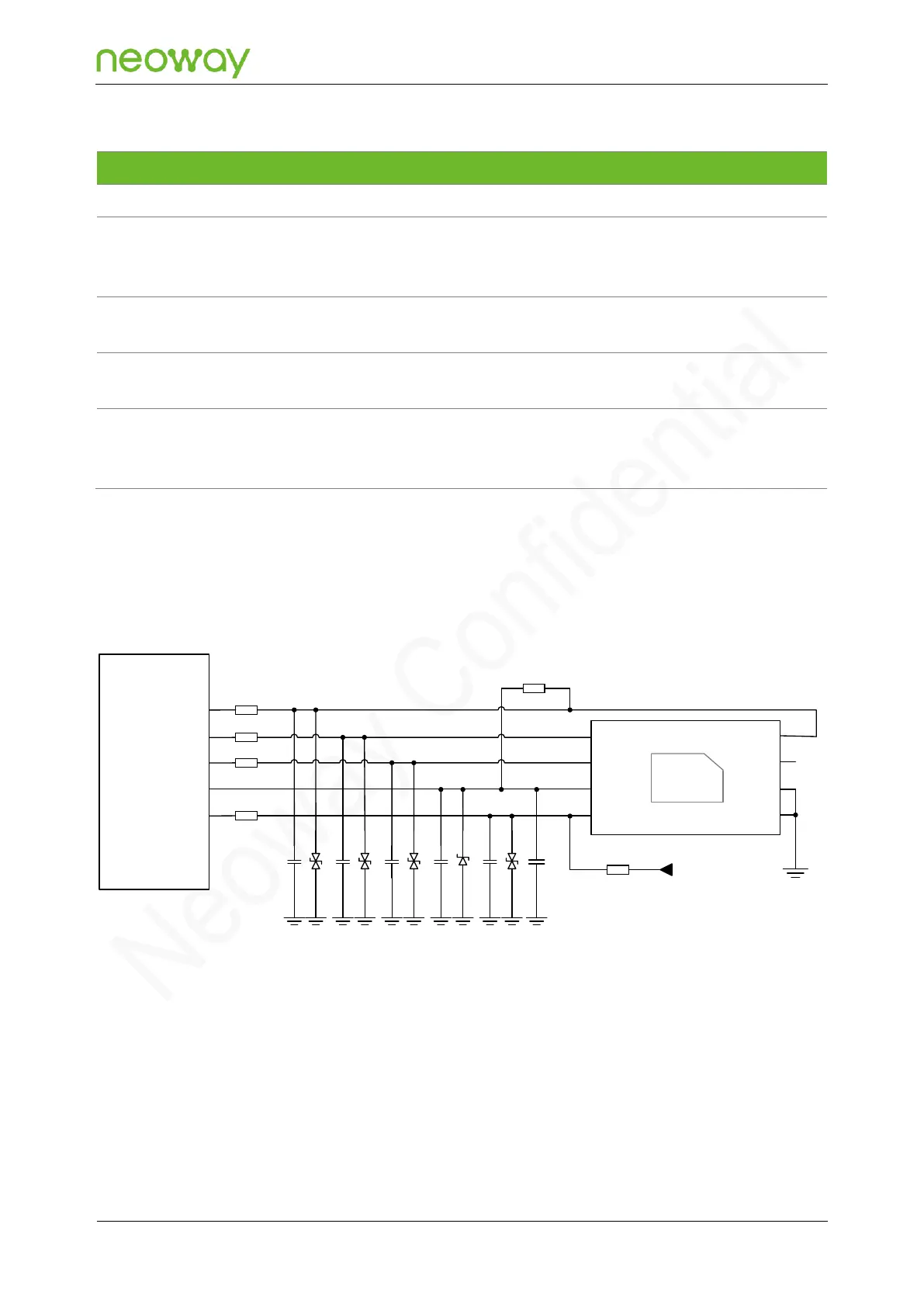
N723-EA provides one USIM card interface. Figure 5-23 shows the reference design of the USIM card
interface.
Figure 5-23 Reference design of the USIM card interface
N723-EA
Module
USIM_DATA
USIM_CLK
USIM_RESET
USIM_VCC
USIM_DET
20Ω
R1
20Ω
R2
20Ω
R3
20Ω
R4
CLK
RST
VCC
DET
DATA
VPP
GND
GND
DNI-47kΩ
R6
VDD_1P8
4.7kΩ
R5
1μF
C6
D5
C5
D4
C4D3
C3
D2
C2
D1
C1
Schematic Design Guidelines:
⚫
USIM_VCC is the pin to supply power for USIM card and its maximum load is 50 mA. It is only
used as power supply for USIM card (forbidden to supply power to other loads).
⚫
Add a pull-up resistor externally to pull up the USIM_DATA pin to USIM_VCC since there is no
internal pull-up on USIM_DATA.