EasyManua.ls Logo

Neoway N723-EA - Sd;Emmc; Figure 5-25 Reference Design of the SDC Interface

Neoway N723-EA
75 pages
Print Icon
To Next Page IconTo Next Page
To Previous Page IconTo Previous Page
Loading...
N723-EA Hardware User Guide
Chapter 5 Application Interfaces
Copyright © Neoway Technology Co., Ltd. All rights reserved.
47
5.3.4 SD/eMMC
Signal
Pin
I/O
Function description
Remarks
SDC_PWR_EN
2
DO
Control of the external power
supply for SD/eMMC
Leave these pins floating if
not used.
SDC_DATA_2
3
B
SD/eMMC data 2
SDC_DATA_3
4
B
SD/eMMC data 3
SDC_CMD
5
DO
SD/eMMC command control
SDC_CLK
6
DO
SD/eMMC clock
SDC_DATA_0
7
B
SD/eMMC data 0
SDC_DATA_1
8
B
SD/eMMC data 1
SDC_DET
96
DI
SD/eMMC detect input
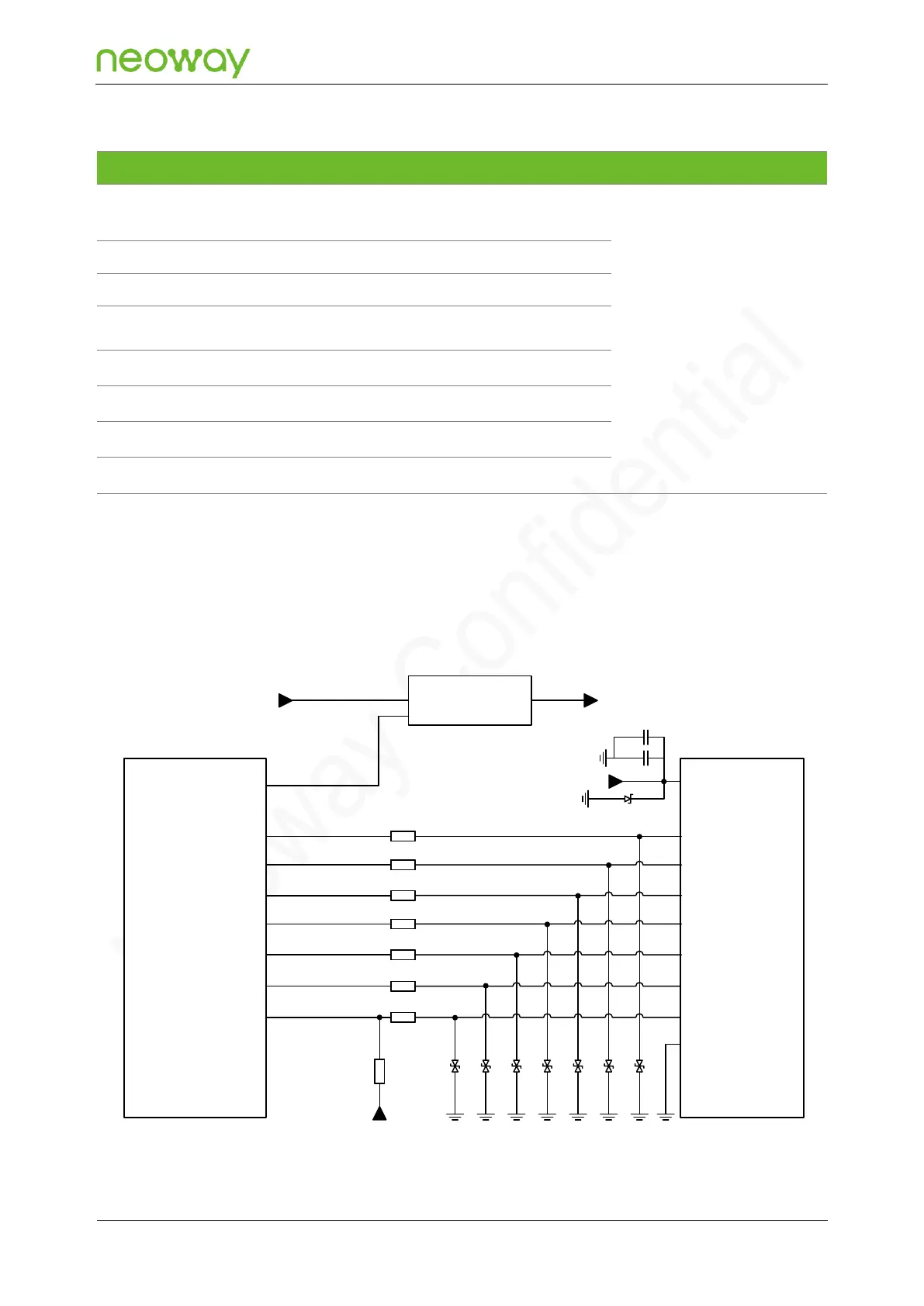
N723-EA provides one SD/eMMC interface, which supports 1.8 V/3.0 V dual voltages, supports clock
frequencies up to HS200-200MHz and DDR50-50MHz, and can be backwards compatible with the DS,
HS, SDR12, SDR25, SDR50, and SDR104 modes. It can be connected to SD card or eMMC chip.
Figure 5-25 Reference design of the SDC interface
SD card
connector
N723-EA
Module
SDC_DATA2
SDC_DATA3
SDC_CMD
SDC_CLK
SDC_DATA0
SDC_DATA1
SDC_DET
DATA2
DATA3
CMD
CLK
DATA0
DATA1
CD
GND
SDC_PWR_EN VCC
V_IN V_SDCARD
V_SDCARD
D2
C2
0Ω
R2
D3 D4 D5 D6 D7 D8
C1
SD Power supply
D1
R1
R3
R4
R5
R6
R7
0Ω
0Ω
0Ω
0Ω
0Ω
10kΩ
R8
VDD_1P8

Table of Contents