N723-EA Hardware User Guide
Chapter 5 Application Interfaces
Copyright © Neoway Technology Co., Ltd. All rights reserved.
MDIO data input and
output
Connecting an external 4.7
kΩ pull-up resistor is
required.
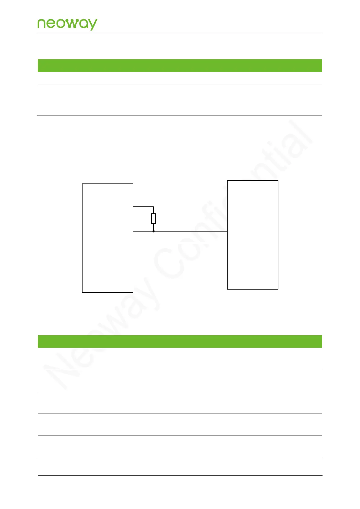
MDIO supports up to 25 MHz frequency and only 1.8 V level. The following figure shows a reference
design of the SDIO interface with a PHY chip:
Figure 5-30 Reference design of the SDIO interface with a PHY chip:
PHY
N723-EA
Module
VDD_1P8
MDIO_DATA
MDIO_CLK
MDIO_DATA
MDIO_CLK
4.7KΩ
R1
Leave this pin floating if it is not
used.
Leave this pin floating if it is not
used.
Leave this pin floating if it is not
used.
Leave this pin floating if it is not
used.
Leave this pin floating if it is not
used.