EasyManua.ls Logo

Neoway N723-EA - Network and Connection; Ethernet; Figure 5-28 Reference Design of the I2 C

Neoway N723-EA
75 pages
Print Icon
To Next Page IconTo Next Page
To Previous Page IconTo Previous Page
Loading...
N723-EA Hardware User Guide
Chapter 5 Application Interfaces
Copyright © Neoway Technology Co., Ltd. All rights reserved.
51
Figure 5-28 Reference design of the I2C
Device
(Slave)
N723-EA
(Master)
VDD_1P8
I2C_SDA
I2C_SCL
GND
I2C_SDA
I2C_SCL
GND
4.7KΩ
R1
4.7KΩ
R2
Schematic Design Guidelines:
If the level of the slave device does not match that of the N723-EA, level conversion is required; see
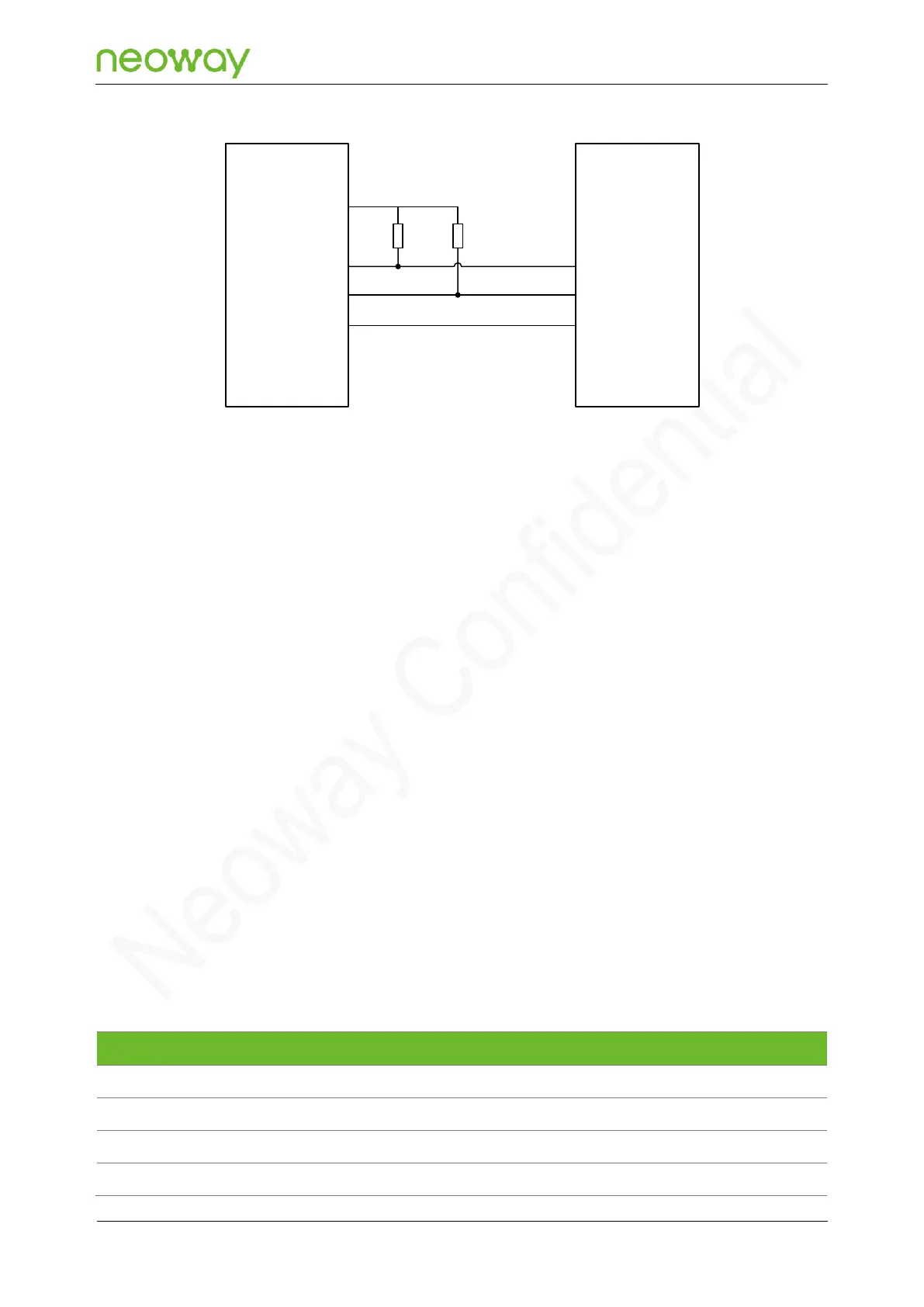
Figure 5-20 Recommended level shifting circuit 1.
PCB Design Guidelines:
Avoid cross routing between the I2C cable and other signal cables as much as possible. If cross-
routing cannot be avoided, keep the signal cables perpendicular to other cables to reduce
coupling.
Keep the signal cables away from areas where static electricity may be introduced as much as
possible.
It is recommended that signal cables be wrapped with left and right ground wires.
5.4 Network and Connection
N723-EA supports Ethernet and Wi-Fi network connection methods.
5.4.1 Ethernet
RMII
Signal
Pin
I/O
Function description
Remarks
RMII_TX_D0
16
DO
Data sending bit 0
Leave this pin floating if it is not used.
RMII_TX_D1
15
DO
Data sending bit 1
Leave this pin floating if it is not used.
RMII_RX_D0
19
DI
Data receiving bit 0
Leave this pin floating if it is not used.
RMII_RX_D1
18
DI
Data receiving bit 1
Leave this pin floating if it is not used.

Table of Contents