EasyManua.ls Logo

Neoway N723-EA - Peripheral Interfaces; Usb; Figure 5-17 Outgoing Call Service Process

Neoway N723-EA
75 pages
Print Icon
To Next Page IconTo Next Page
To Previous Page IconTo Previous Page
Loading...
N723-EA Hardware User Guide
Chapter 5 Application Interfaces
Copyright © Neoway Technology Co., Ltd. All rights reserved.
39
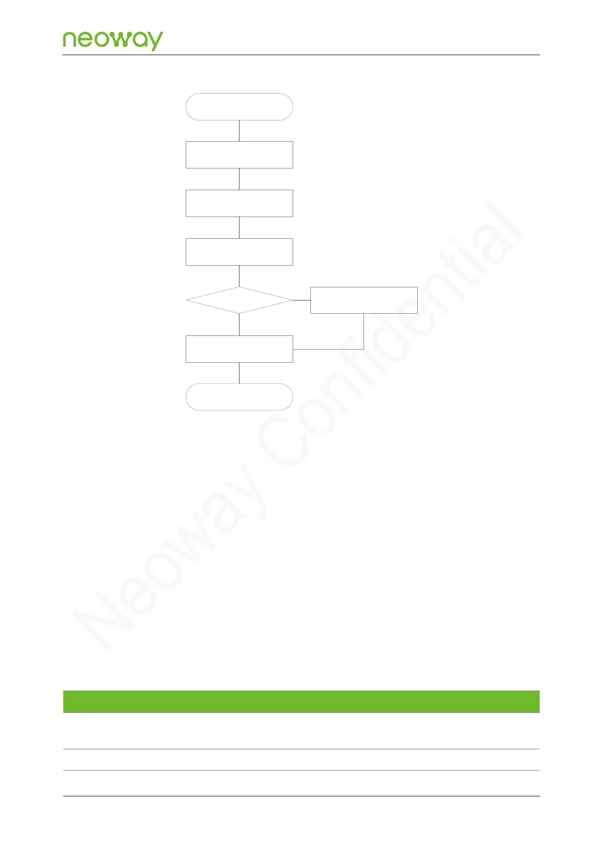
Figure 5-17 Outgoing call service process
5.3 Peripheral Interfaces
N723-EA provides various peripheral interfaces.
In all reference designs of this section, the receiving and sending directions included in the pin names
of the peripheral interface of the module are based on the module, whereas peripheral pins are named
based on the components. For example, UART_TXD indicates the pin used by the module to send
data, and MCU_RXD indicates the pin used by the MCU to receive data. These two pins should be
connected.
In the process of MCU selection and design, note whether the signal naming of pins is based on the
module or the MCU.
5.3.1 USB
Signal
Pin
I/O
Function description
Remarks
USB_VBUS
40
PI
USB insertion detection
pin
USB_VBUS=3.5 V - 5.2 V, typical value:
5.0 V.
USB_DM
41
IO
USB data negative signal
USB 2.0. This pin is used for software
Sleep mode
Initiate an outgoing
service
MCU pulls SLEEP pin
high
Enable UART and process
outgoing service
Wait till service is
processed
Complete service
processing?
End
MCU pulls SLEEP pin
low
N
Y

Table of Contents