EasyManua.ls Logo

Neoway WM620 - Pin Definition

Neoway WM620
46 pages
Print Icon
To Next Page IconTo Next Page
To Previous Page IconTo Previous Page
Loading...
WM620 Hardware User Guide
Copyright © Neoway Technology Co., Ltd
5
The figure shows main application pins. Select pins based on product requirements and leave pins
that are not used unconnected.
For more details about pins, see the pin description.
JTAG pins have not be open to customers.
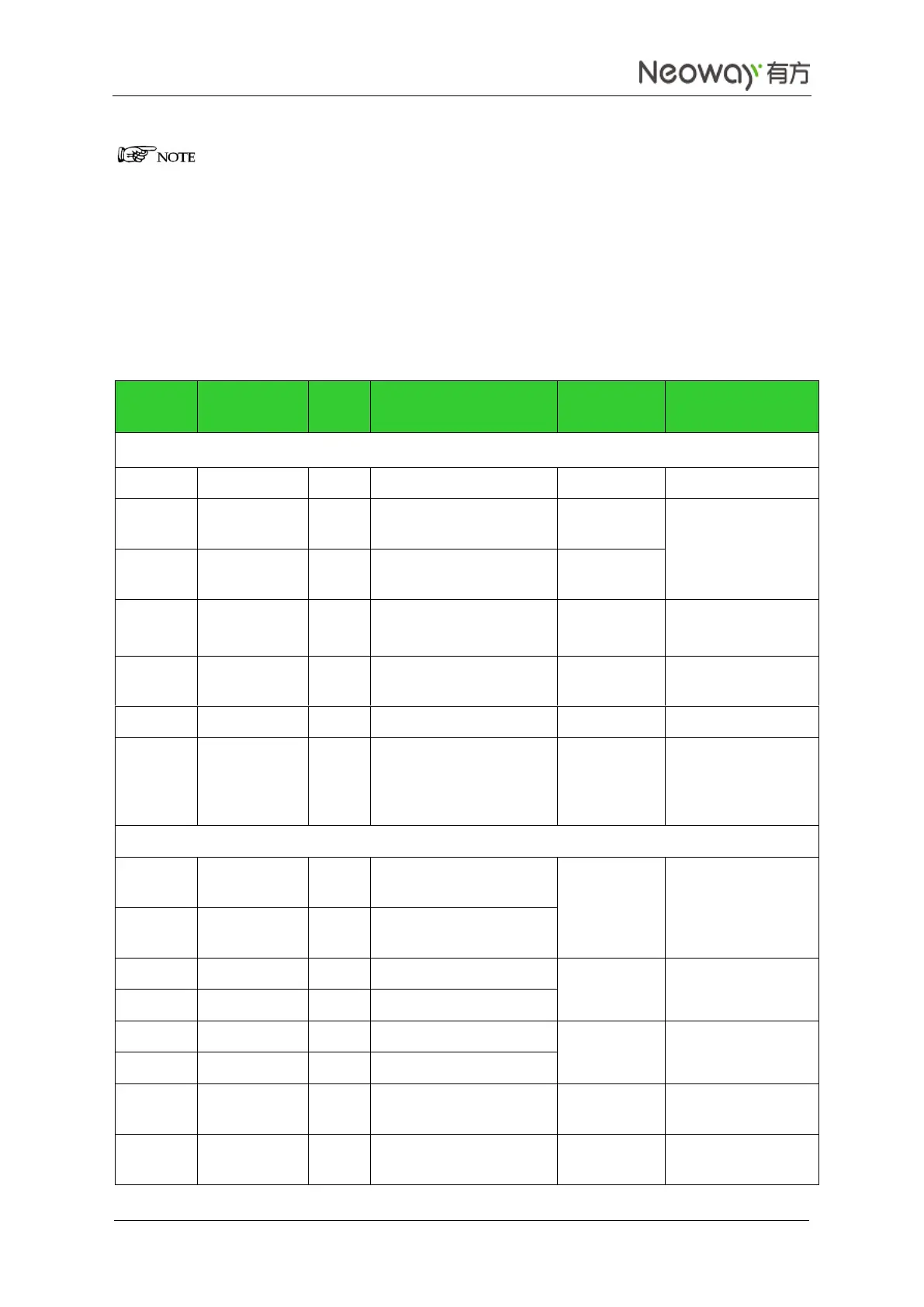
2.2 Pin Definition
Table 2-1 WM620 pin definition
Pin No.
Pin Name
I/O
Function
Level
Feature (V)
Remarks
Power Supply and Switch Interfaces
22, 23
VBAT
PWR
Main power supply
3.3 V to 4.2 V
26
VDD_1.8V
PWR
1.8 V power supply
output
Continuous voltage
output after the
module is on
27
VDD_2.6V
PWR
2.6 V power supply
output
47
VRTC
PWR
RTC power supply I/O
1.5 V to 3.25 V DC
Typical value: 3.0 V
46
ON_OFF
I
On/Off control
Internally pulled up
to 1.8 V by 200K
25
RESET
DI
Hardware reset pin
VDD_1.8V
1, 12, 17,
21, 24,
34, 43,
45, 50, 61
GND
PWR
Ground
Audio Interface
28
EAR_P
AO
Earphone amplifier
output (+)
Keep not connected
(NC) if not used
29
EAR_N
AO
Earphone amplifier
output (-)
30
MIC_1N
AI
Microphone #1 input (-)
Keep NC if not used
31
MIC_1P
AI
Microphone #1 input (+)
32
MIC_2P
AI
Microphone #2 input (-)
Keep NC if not used
33
MIC_2N
AI
Microphone #2 input (+)
35
SPK_P
AO
Speaker amplifier output
(+)
Keep NC if not used
36
SPK_N
AO
Speaker amplifier output
(-)
Keep NC if not used

Table of Contents

Related product manuals