WM620 Hardware User Guide
Copyright © Neoway Technology Co., Ltd
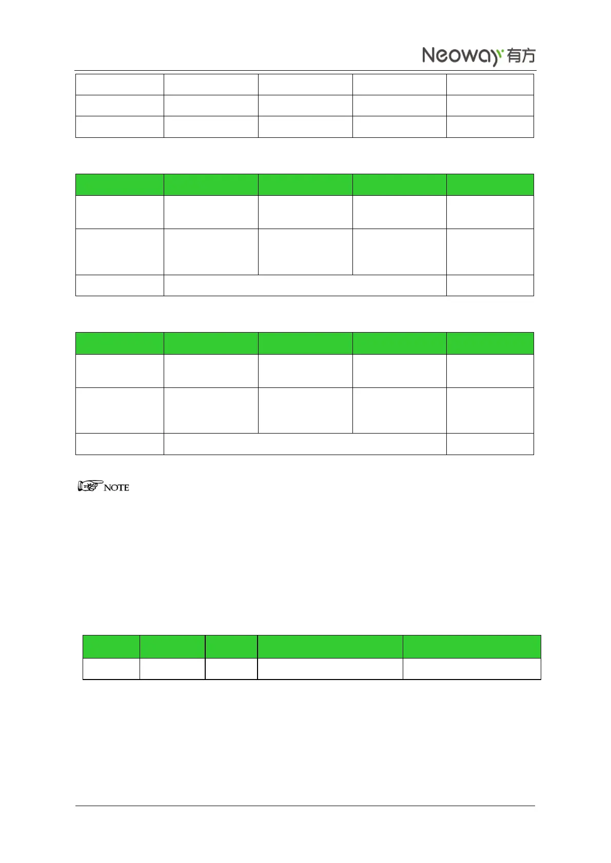
Table 3-11 EAR parameter
Impedance
between EAR_P
and EAR_N
Table 3-12 SPK parameter
Impedance
between SPK_P
and SPK_N
Audio signals are analog and should be protected from interference and ESD.
Differential signal trace is required for dual-ended signals.
Users can add audio amplifier to output circuits to enhance the audio signals.
Do not ground the audio output pin directly. Otherwise, some abnormity might occur to the module.
Do not miss match the I/O pins of two audio channels because they are fixed inside the module.
3.8 ADC
Connect to GND if not used
The 49
th
pin can convert a channel of analog signal to digit signal, that is, it can quantize the voltage
signals and temperature signals using 12-bit digit signals. Users can use the AT+GETADC command to
query. For more information, refer to Neo_WM620 WCDMA Module AT command Set.