WM620 Hardware User Guide
Copyright © Neoway Technology Co., Ltd
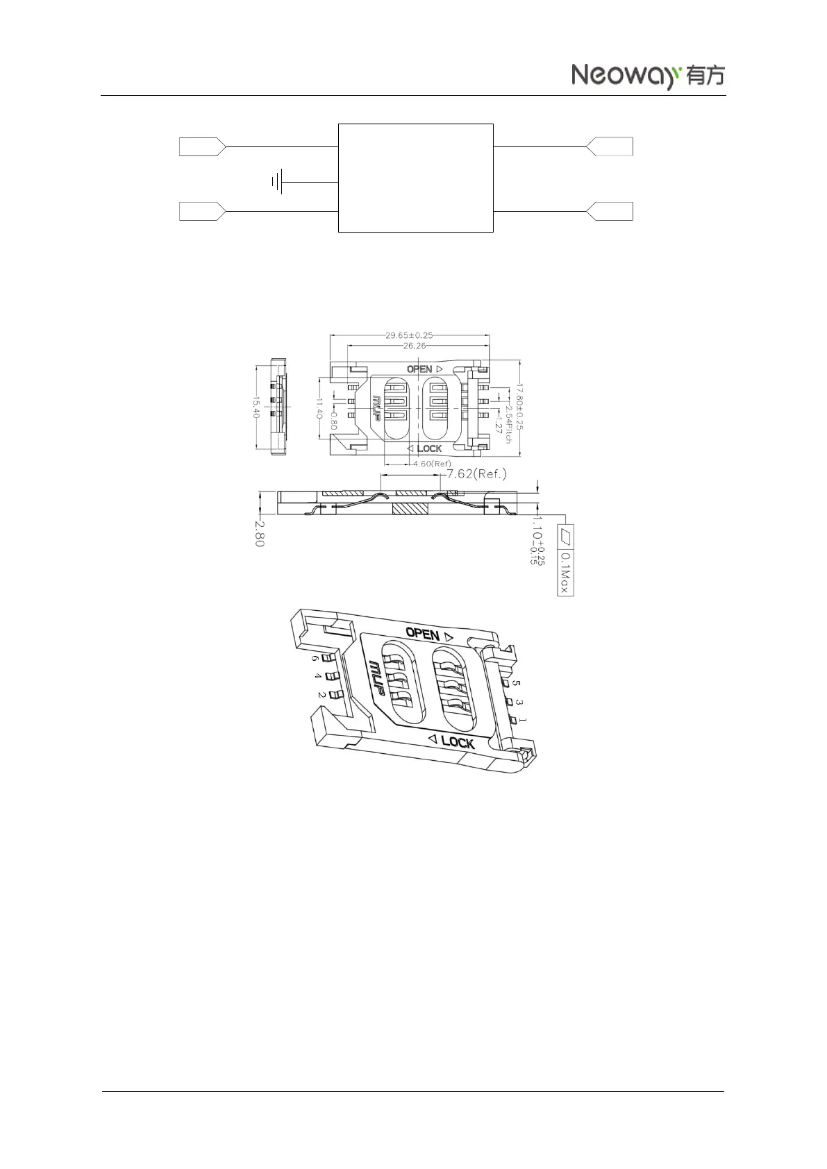
Figure 3-14 Recommended ESD diode array
If 6-pin SIM card sockets are used, MCP-C713(H2.8) is recommended. Figure 3-15 shows its
encapsulation.
Figure 3-15 Reference of SIM card socket
The pins of USIM card socket:
Pin 1 USIM_CLK
Pin 2 USIM_ DATA
Pin 3 USIM_RST
Pin 4 USIM_VPP
Pin 5 USIM_VCC
Pin 6 GND
USIM signals are sensitive to RF interference. Therefore, it is recommended to add high-performance
ESD components if required.
The PCB design should meet the following requirements:
Avoid bifurcation at PCB trace of SIM_CLK.
Ensure as short PCB traces of USIM_DATA and USIM CLK as possible and surround the traces
with GND copper.
RF traces or RF connector should be far away from the USIM card and USIM card traces.
L1
GND
L2
L3
L4
1
2
3
4
5
USIM_RST
USIM_CLK
USIM_DATA
USIM_VCC