WM620 Hardware User Guide
Copyright © Neoway Technology Co., Ltd
Ensure that the USIM traces are as smooth as possible.
Place ESD diodes or filter capacitors close to the USIM card.
3.4 USB Interfaces
Table 3-7 USB interface
High-speed USB differential data, (+)
High-speed USB differential data, (-)
Input voltage 3.3 to 5.5 V.
The WM620 module is compliant with USB 2.0 full speed device. The USB 2.0 specification requires that
the hosts such as computers support three USB speeds: low-speed (1.5 Mbit/s), full-speed (12 Mbit/s) and
high-speed (480 Mbit/s).
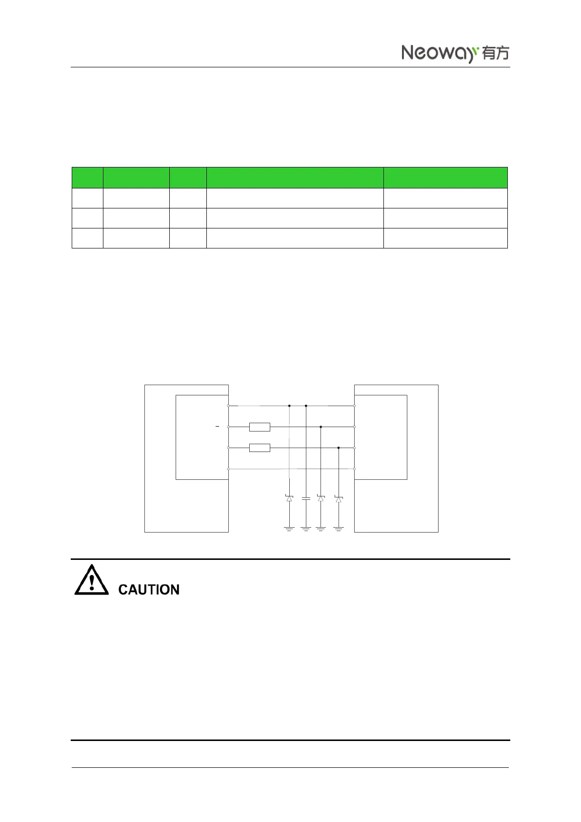
The V_USB pin is a USB power supply input. Parallel ESD diodes respectively close to the three signals.
The following circuit between the module and a computer is recommended.
Figure 3-16 Reference USB circuit
The USB circuit design should comply with the USB 2.0.
The traces of USB_D+ and USB_D- must be routed as a group of differential pair with 90 Ω differential
impedance.
The USB differential pair should be routed side-by-side and on the same layer.
USB_D+ and USB_D- is a pair of high speed signals, so the trace lengths should match as well as
possible.
USB interface must be connected or set aside the relevant test points to facilitate subsequent firmware
upgrade or debugging.
DCE
V_USB
USB_D
USB_D+
GND
DTE
UTXD
URXD
RTS
CTS
VBUS
USB_DM
USB_DP
GND
20
20