WM620 Hardware User Guide
Copyright © Neoway Technology Co., Ltd
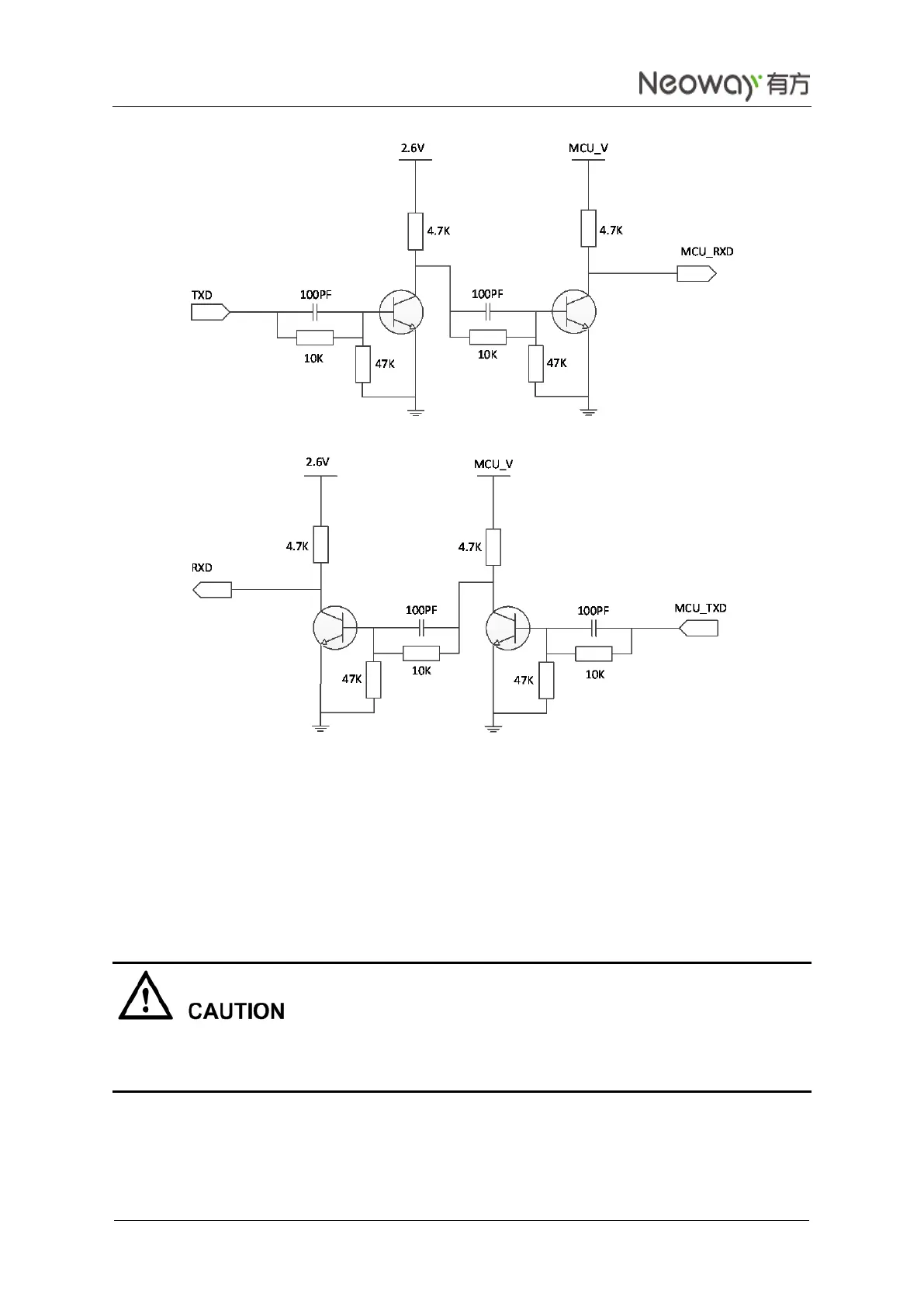
Figure 3-19 Recommended circuit between 5V MCU and UART
Reference components:
Crystal: MMBT3904 or MMBT2222. High-speed transistors are preferred.
Logic level: DTE 5 V -> DCE 2.6 V
Figure 3-19 shows the circuit between MCU TXD and RXD/TXD of the module. In the circuit, MCU_V
supplies 5 V.
Avoid spark or fault on UART during the power-on procedure of the module.
Do not send any data to UART within 5 seconds after the module is turned on.
3.6 Sleep Mode
The sleep mode of WM620 is controlled in two ways: UART and USB. The module can receive voice and
SMS message in sleep mode controlled by UART or USB. Upon receiving SMS messages, voice, or data,