WM620 Hardware User Guide
Copyright © Neoway Technology Co., Ltd
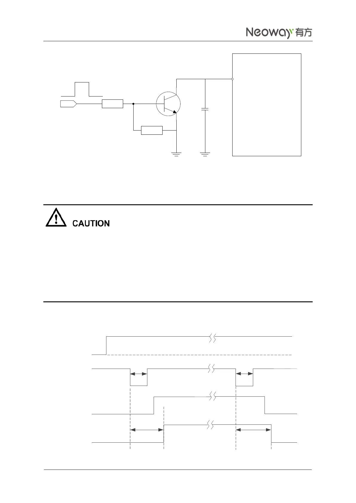
Figure 3-6 Reference circuit of ON_OFF controlled by high level
The ON_OFF pin might encounter pulse interference generated by ESD. It is recommended to parallel a
10 nF capacitor connected to the ground to protect the ON_OFF pin.
It is not recommended to connect the ON_OFF pin to ground to start the module because it will affect the
ESD feature of the module.
The ON_OFF pin can control the module startup and shutdown. Do not repeat triggering this pin.
Otherwise, the startup or shutdown might fail. For example, the user plans to start up the module but gives
low level pulse for twice, resulting in shutdown.
The shutdown function of the ON_OFF pin is controlled by the software. If the software is not running
properly, the module cannot shut down properly.
Figure 3-7 shows the power-on procedure of the WM620 module.
Figure 3-7 Power-on procedure
WM620
ON_OFF
2K
10K
VT2
MCU ON_OFF
10 nF
C3
C3 is close to the pin.
VBAT
ON_OFF
RESET_N
0.5s<t<1s
1.6V<V
H
V
L
<0.5V
USB_DP
2.5s<t<5s
Power-on
Procedure
Power-off
Procedure
4s
4.6s