WM620 Hardware User Guide
Copyright © Neoway Technology Co., Ltd
3.5 UART
Table 3-8 UART
High-speed UART to send data
High-speed UART ready for receiving data
High-speed UART receive data input
(allow 3 V input at most)
High-speed UART transmit data output
3.5.1 Basic Descriptions of UART
UART is used for AT commands, data sending/receiving, etc.
The UART of WM620 works at 2.6 V CMOS logic level. The voltages for input high level should not
exceed 3.0 V. Supported baud rates are 300, 600, 1200, 2400, 4800, 9600, 14400, 19200, 38400, 57600,
115200, 230400, 460800, 921600 bit/s, and the default rate is 115200 bit/s.
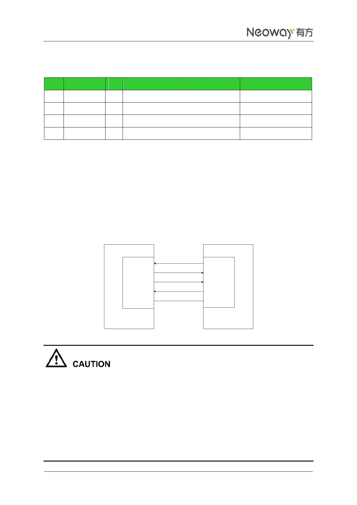
Figure 3-17 shows the signal connection between the module (DCE) and the terminal (DTE).
Figure 3-17 Signal connection between DCE and DTE
The hardware flow control of the WM620 module is disabled by default. Use AT+IFC=2,2 to enable the
hardware flow control function and disable it by running AT+IFC=0,0. The setting will not be saved after
the module is shut down. For more details about the commands, see Neo_WM620 WCDMA Module AT
Command Set.
The hardware flow control is implemented by AT commands together with CTS. After using the AT
commands to enable the hardware flow control function, set CTS low level so that the module can
communicate via UART port. If the CTS pin is set to high level, the UART port cannot
communicate.
Leave CTS and RTS not connected if the hardware flow control function is not required.
RXD
TXD
RTS
CTS
UTXD
URXD
CTS
RTS
GND GND
DTEDCE