WM620 Hardware User Guide
Copyright © Neoway Technology Co., Ltd
5 Electric Features and Reliability
5.1 Electric Feature
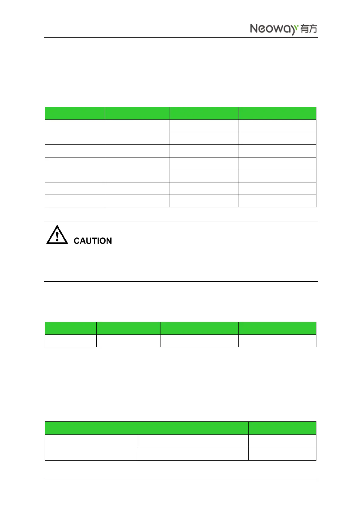
Table 5-1 Electric feature of the module
Refer to the level design circuits for the output pins of the module.
For input pins, design their circuits strictly complying with their voltage ranges. Ensure that the level at
the input pin is not greater than 0.5 V. Otherwise, the module cannot identify the level correctly.
5.2 Temperature
Table 5-2 Temperature Feature (Unit: ºC)
5.3 Current
Table 5-3 and Table 5-4 lists the current of WM620 in different modes at 25 ºC and 3.9V. During the test,
the USB is disconnected.
Table 5-3 Operating current (Unit: mA)