WM620 Hardware User Guide
Copyright © Neoway Technology Co., Ltd
3.7 Audio Interface
Table 3-9 Audio interface
Earphone amplifier output (+)
Receiver or 32Ω earphone
driving output
Earphone amplifier output (-)
Speaker amplifier output (+)
Speaker amplifier output (-)
Audio channels are switched by executing AT+HANDFREE commands: AT+HANDFREE=0 for
receiver mode; AT+HANDFREE=1 for speaker mode. For more details about audio channel switch, see
Neo_WM620 WCDMA Module AT Command Set.
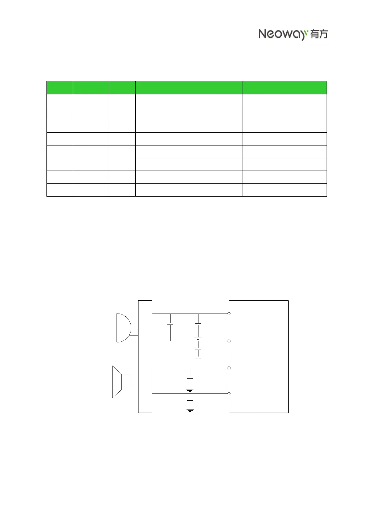
The following figures shows typical audio interfaces of WM620. The earphone output pins are directly
connected to the receiver. Parallel a bypass capacitor for each pin. The capacitor of 100 pF or less is
expected to optimize performance in each design. The output power for the different earphones is
typically 35 mW for a full-scale +3 dBm sine wave into a 32 Ω speaker.
Figure 3-23 Reference design of MIC differential connections
WM620
MIC1P
MIC1N
100 pF
33 pF
100 pF
100 pF
EAR_P
EAR_N
Earpiece
32-Ohms
MIC
33 pF
ESD Protection