WM620 Hardware User Guide
Copyright © Neoway Technology Co., Ltd
3.2 Running Status Indication
3.2.1 LED Indicator
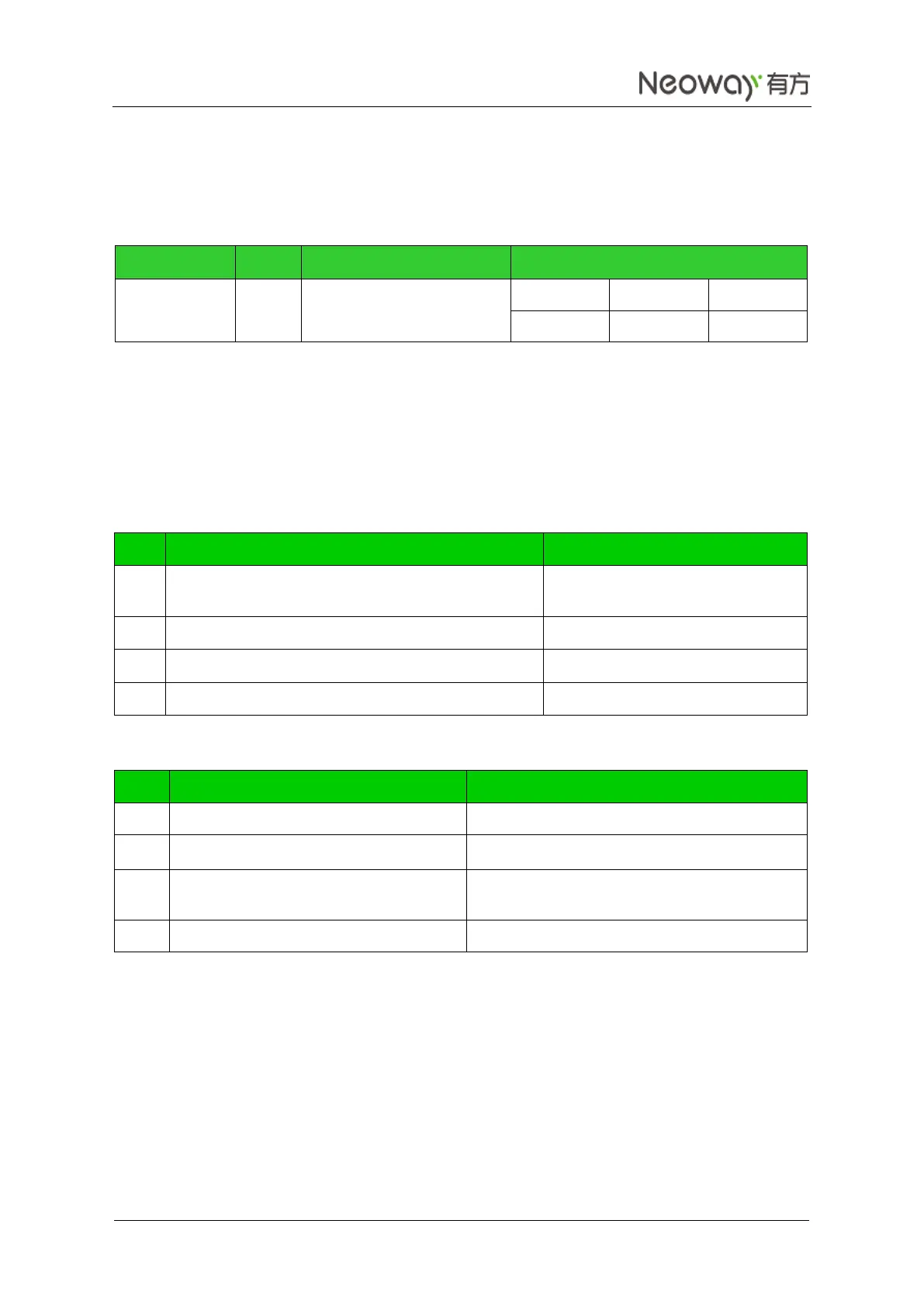
Table 3-3 LED indicator
When the module is running, the LED indicator is driven by the SIG_LED to indicate different running
status with its various blink behaviors. For details, see Neo_WM620 WCDMA Module AT Command Set.
Table 3-4 shows the default LED indication. The AT+SIGNAL=1 command allows users to modify it to
the indication status in Table 3-5.
Table 3-4 Network status indication (a)
Network is restricted; No SIM card; PIN is required;
Searching network; User authentication
PDP activated, obtained IP address
Socket link has been set up
Blink (0.2s OFF/ 1.8s ON)
Table 3-5 Network status indication (b)
Have registered 2G network and been idle
Blink (500ms ON / 1500ms OFF)
Have registered 3G network and been idle
Blink (100ms ON / 2900ms OFF
)
Blink twice (100 ms ON/100 ms OFF/100 ms
ON/2700 ms OFF)
Blink (125ms ON /125ms OFF)
The LED can be directly connected to this pin with a resistor in series. For better luminance, drive the
LED with a transistor instead. The LED's brightness depends on the value of R1 and VCC.