WM620 Hardware User Guide
Copyright © Neoway Technology Co., Ltd
Users can change the pulse periods via AT commands. For details, see Neo_WM620 WCDMA
Module AT Command Set.
3.3 USIM Card Interface
Table 3-6 SIM Card Interface
SIM card data input/output
WM620 supports 3.0 V and 1.8 V USIM cards. USIM_DATA need to be externally pulled up to
USIM_VCC by a 10 KΩ resistor. USIM_CLK works at 3.25MHz typically.
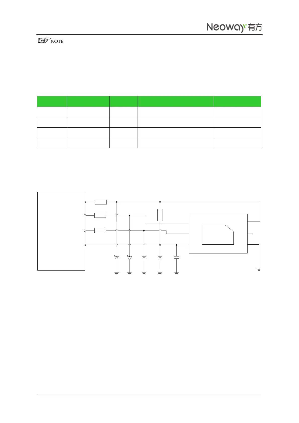
Figure 3-13 Reference design of USIM card interface
Figure 3-13 shows reference circuit design of the USIM card. ESD protectors, such as ESD diodes (lower
than 33 pF) or ESD varistors, are recommended on the USIM signals, especially in automotive electronics
or other applications with badly ESD. In Figure 3-13, T1 to T4 should be placed close to the USIM socket.
In other applications, replace ESD diodes with 22 pF to 33 pF grounding capacitors. The total distributed
capacitance, including the junction capacitance of the ESD diode or other devices, cannot be greater than
120 pF.
20
20
20
1 uF
USIM_DATA
USIM_CLK
USIM_RST
USIM_VCC
WM620
CLK
RST
VCC
VPP
GND
DATA
T1
T2
T3 T4
C1
10K
USIM Card