BTS User Manual
Neware Technology Ltd.
http://www.newarebattery.com
most.
3 “In the calibration mode of "Calibrate first and then test accuracy", the current calibration points and voltage
calibration points are "4-section calibration" by default, and the calibration points can also be modified to
"9-section calibration" at most.
4 The lowest value is 10%, and the highest value is 95% (the highest value of the three-section calibration is 90%),
and the high value of each section must be greater than the low value. Starting from the second row, the low value
of each row is equal to the high value of the previous row. Users can set the low value and high value as required.
5 The default precision is 1‰ and changeable.The smaller the accuracy, the more accurate the calibration or test.
3. Start calibration
Click Start calibration. The software starts to calibrating. The "Precision Test" mode displays as "Start test," while the
"Calibrate before Precision Test" mode displays "Start calibration and test."
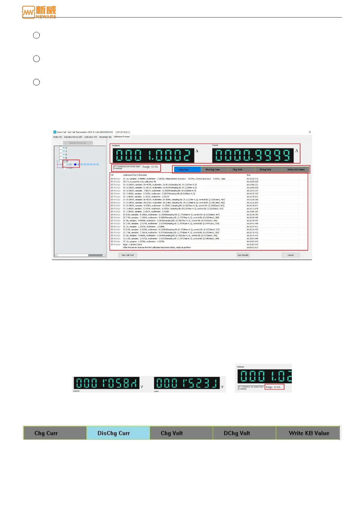
7.2. Check Real-time Data
Click the "View real-time data" button, and the real-time data display interface pops up, as shown below:
Figure 7-8 Real-time data display
The data display interface is mainly divided into the following areas: equipment list area, multi-meter and channel value
display area, range display area, progress display area, and calibration/test status information display area.
1. Equipment list area
Display equipment status during calibration. If the calibration passes, mark "√". If the calibration does not pass, hit "×".
The calibration criteria are a "green triangle," as shown in the figure above.
2. Muti-meter and channel value display area
The current and voltage values collected by the multi-meter and channel are displayed in A/V, as shown in Figure 7-9:
3. Range display area
The range display area displays the total range of voltage and current, calibration status, and the percentage of
calibration range end value, as shown in Figure 7-10:
Range: When calibrating or testing the current of the equipment, display the total current range, in unit A. When
calibrating or testing the voltage of the equipment, the total voltage range is displayed in V.
Figure 7-9 Multi-meter and channel values display Figure 7-10 Range display area
4. Process display area
As shown in Figure 7-11, the calibration and testing progress of the channel is displayed, and the current step will be
highlighted.
Figure 7-11 Step process display area
5. Calibration/test status and information display area
Display channel calibration status and calibration/test information. As shown in Figure 7-12.