BTS User Manual
Neware Technology Ltd.
http://www.newarebattery.com
area, and the voltage and current displayed are the range of the equipment; Other
parameter names correspond to the parameter values of the channel on the right. The following figure shows that the
current device is 5V6A.
2. Channel legend analysis:
The device is not connected to the server, and no channel status is displayed. When the device is connected to the
server, the status (Stop, Protect, Suspend, Pause, Complete) of the channel is displayed.
When the channel is operating, the blue dynamic downward arrow indicates the charging process, the red
dynamic upward arrow indicates the discharge process, indicating the suspension state of the test,
indicate Stop, indicate REST, indicate the channel protection state, indicate complete, indicate the
channel disabled state. indicate the pulse.
Channel information display button . You can click this button to view the channel information.
Click the button to display the auxiliary channel relationship. Click the button to view the corresponding
auxiliary channel bound to the main channel.
Click the AUX channel display button , open the aux channel display window and you will see the voltage and
temperature information.The AUX display button will be displayed on the channel icon only after the AUX is
bound to the battery test channel and the aux field is set in the step.
Figure 4-10 Equipment information display Figure 4-11 AUX channel information
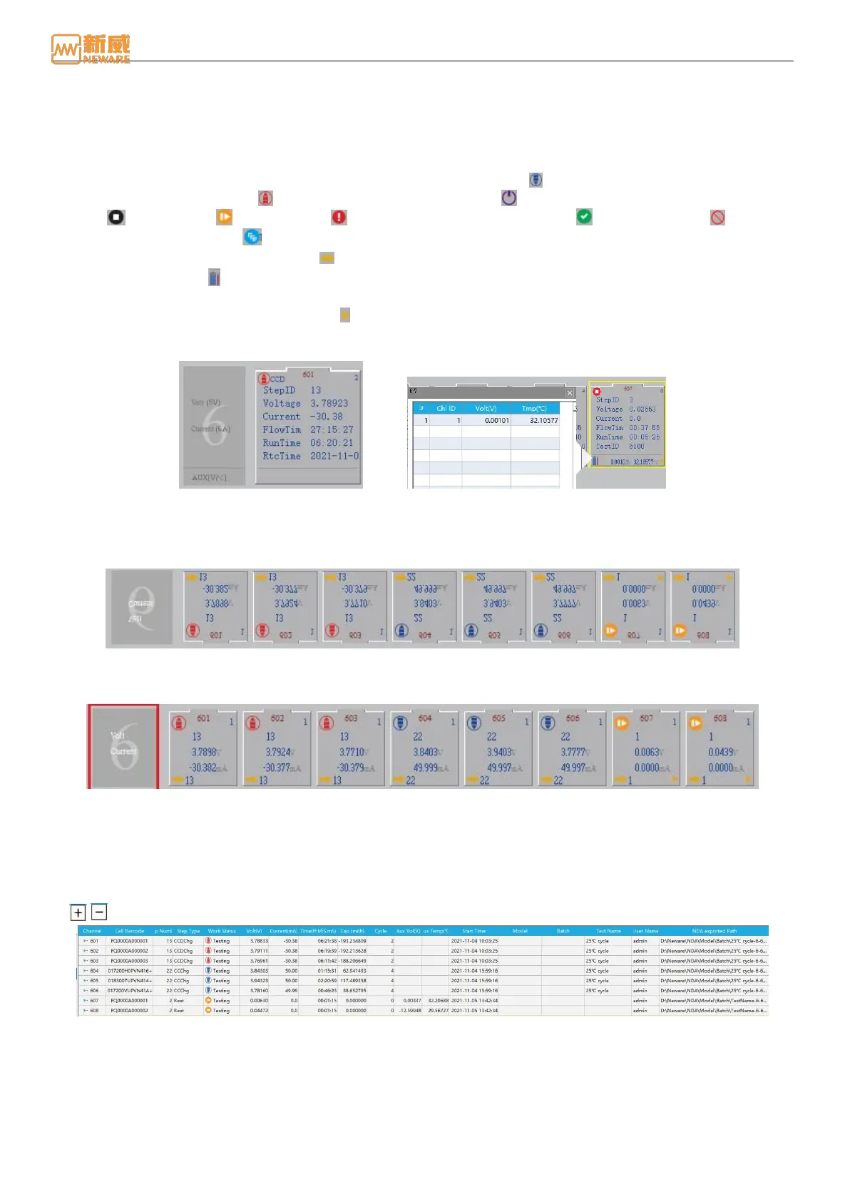
Small Icon
The small icon display is composed of a simulated small battery icon shape and corresponding channel data, as shown in
the figure below:
Figure 4-12 Small icon visualize display
1. Device information display: The parameter name displayed in the device information display area corresponds to the
parameter value on the right channel. As shown in the following figure, the number 1 indicates the unit number:
Figure 4-13 Device information display
2. As shown in the figure above, the channel icon are displayed: channel number, step number, execution status (charge,
discharge, rest, and so on), real-time voltage, and real-time current.
List Display
The real-time data information of each channel is displayed in a list. You can customize the displayed data items and
arrange the data items in ascending or reverse order. The list display interface is as shown in the figure below. Select
the / button below the channel number to view/hide the information related to the Aux under the channel.
Figure 4-14 List visualize interface
1. Main list customization: Users can customize the display of test data fields as required. Right-click the table header
and select the data field that you want to display from the drop-down list, as shown in the following figure: