BTS User Manual
Neware Technology Ltd.
http://www.newarebattery.com
2.6. Connection of Test Equipment
This section describes how to connect the tester. The following uses the BTS9008 as an example:
1. Power connection
This device uses a three-core power cord to connect to the power socket of the mid-machine and then to the grid.
Attention: Please note that the input voltage. Grounding terminal is effectively grounded!
2. Mid-machine connection
The mid-machine is connected to the BTS9.1 upper-machine through TCP/IP port.
Attention: Pay attention to fire prevention and keep away from flammable objects.
3. Aux connection
The aux is connected internally with the mid-machine to realize communication without external connection.
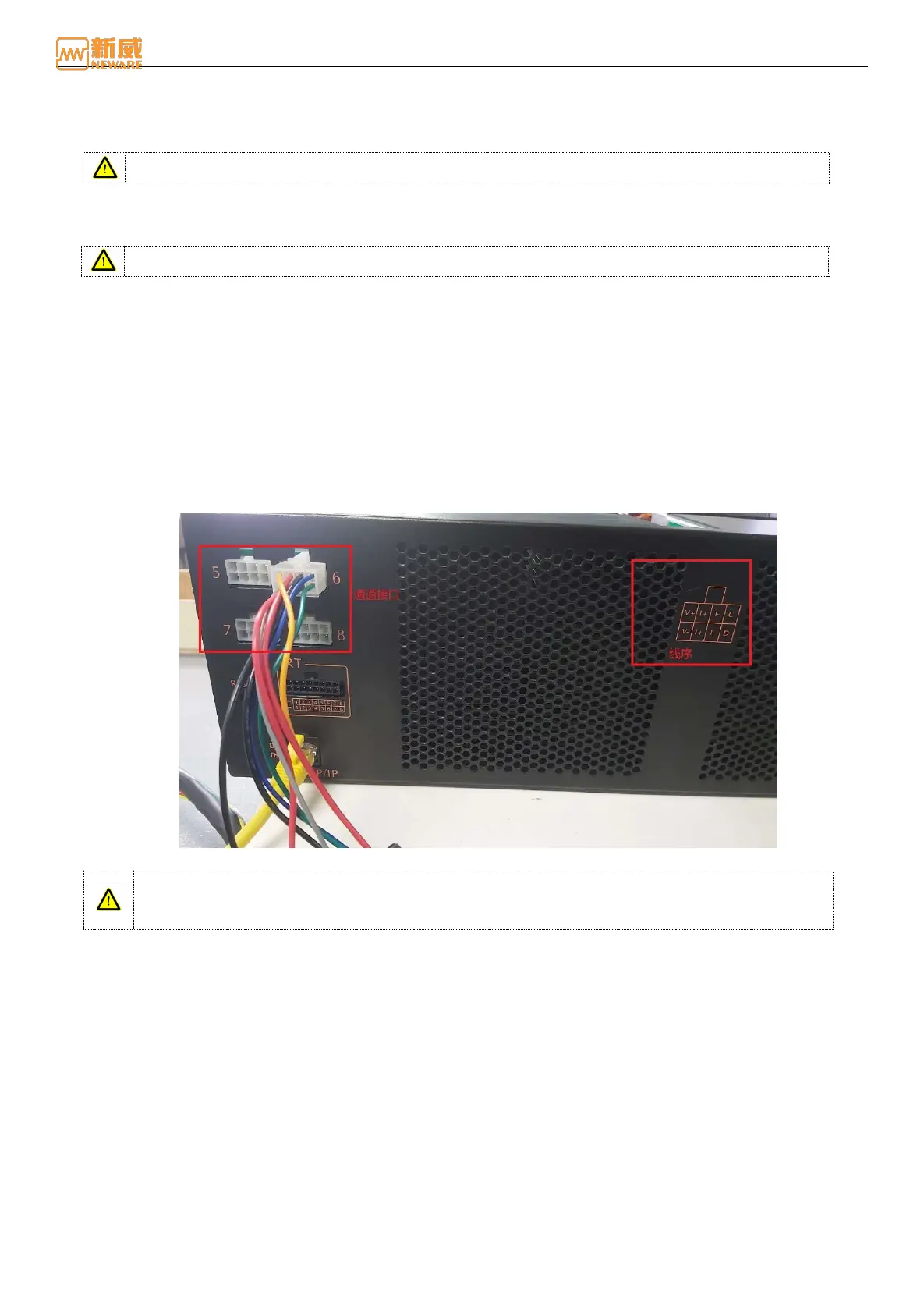
4. Battery connection
When connecting the battery, the current/voltage cable and communication cable of the battery have a strict
corresponding relationship with the cable sequence on the channel interface. Please check the cable sequence of the
channel interface carefully when connecting the device as shown in the figure below).
V+:Cathode Voltage V-:Anode Voltage I+:Cathode Current I-:Anode Current C
:
SCL clock line D
:
SDA data cable
Figure 2-10 Channel wire connection
Warning: When connecting the battery to the clamps, ensure that the cathode and anode of the
battery are correctly connected to the positive and negative terminals of the clamps to prevent
accidents during the test.