4
2.3 Detector Connection and Setup
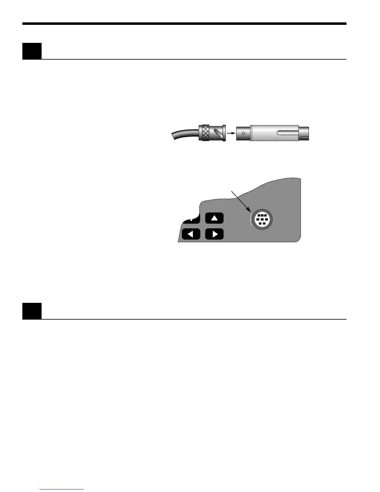
Connect the detector to its calibration module as shown in Figure 3. The
detector’s model and serial numbers must match the model and serial
numbers found on the calibration module. Insert the calibration module,
with its groove facing left, into the connector port on the front panel of the
1830-C, as shown in Figure 4. An alignment pin assures the proper orienta-
tion of the calibration module.
Detector Cable BNC Calibration Module
Figure 3. Connecting a Detector with its Calibration Module
Plug calibration
module into this port.
INPUT
Figure 4. Calibration Module Connector Port
NOTE
Always power off the meter before removing or inserting the calibration
module.
2.4 Configuring the Computer Interface
The RS-232C baud rate and the IEEE 488 GPIB address must be properly set
via the back panel system switches if either interface is to be used. Please
refer to Section 6 for detailed instructions.

 Loading...


