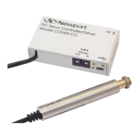
Chapter 3 Laser Diode Driver Operation 21
3.3.1 External Modulation BNC
CAUTION
Do not connect or disconnect a signal to the
modulation input with the laser on.
A BNC connector is provided for an external modulation signal. See section
3.5.4 for a description of modulation setup.
Each 100 mV change in the modulation input is equal to 1% of the
maximum drive current of the driver. However, regardless of the input
voltage, the current cannot exceed the current limit.
3.3.2 Detector BNC
CAUTION
Do not disconnect the detector with the laser on.
A BNC connector is provided for detector connections, with the center pin
the cathode connection and the outer shell the anode connection for
photodiodes. For thermopiles, the positive lead goes to the center and the
negative lead goes to the shell. It is the same input as pins 3 and 4 in the 9-
pin D connector.
3.3.3 Interlock
The interlock pins, 1 and 2, must be connected together to complete the
circuit and allow the laser operation. Internally, pin 1 is connected to a +5V
supply through a 10 k
Ω
resistor and pin 2 is connected to ground through a
220 Ohm resistor.
3.3.4 Aux. Thermistor
A standard 10k
Ω
thermistor can be used to monitor external temperature.
When not using this connection, place a 10k
Ω
resistor across pins 6 and 7. In
this case the Taux reading will always be approx. 25
°
C.
Artisan Technology Group - Quality Instrumentation ... Guaranteed | (888) 88-SOURCE | www.artisantg.com
 Loading...