GEO S12 GENERAL SET-UP INSTRUCTIONS Page 13/106
Remove the connector panel so that filter WAGO connectors become accessible;
In Passive Mode, connector A (from filter) should be inserted in connector B (PCB
“Passive In”), and Connector D (“Passive Out”) should be connected to speakers via
connector C.
In Active Mode, WAGO Connector A (from filter) should be directly connected into
speakers via connector C (PCB connectors B & D are then unused).
2.1.4 Cabling
NEXO recommends the exclusive use of multi-conductor cables to connect the system: the cable kit is
compatible with all the cabinets, and there is no possible confusion between LF, MF and HF sections.
Cable choice consists mainly of selecting cables of the correct sectional dimension (size) in relation to
the load resistance and the cable length. Too small a cable section will increase both its serial resistance
and its capacitance; this reduces the electrical power delivered to the loudspeaker and can also induce
response (damping factor) variations.
For a serial resistance less or equal to 4% of the load impedance (damping factor = 25), the maximum
cable length is given by:
L
max
= Z x S S in mm
2
, Z in Ohm, L
max
in meters
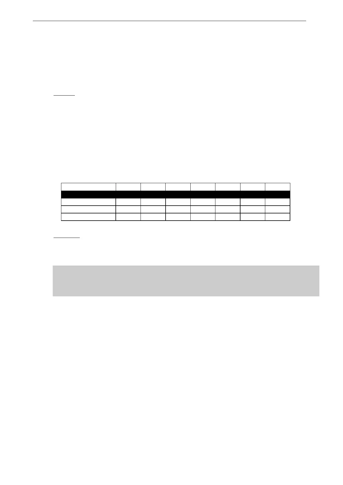
The table below indicates these values, for 3 common sizes.
2.1.5 Example:
GEO S12 has a 16 Ohms nominal impedance in passive mode, so 4x Geo S12 wired in
parallel will present a 16/4 = 4 Ohm load impedance. The maximum acceptable 2x2.5
mm
2
(AWG #12) cable length L
max
for such a cluster is 10 meters.
IMPORTANT
Long speaker cables induce capacitive effects – up to hundreds of pF depending on the
quality of the cable - with a low-pass effect on high frequencies. If long speaker cables
must be used, ensure that they do not remain coiled while in use.