Page 56/106 GEO S12 HARDWARE SETUP PROCEDURE
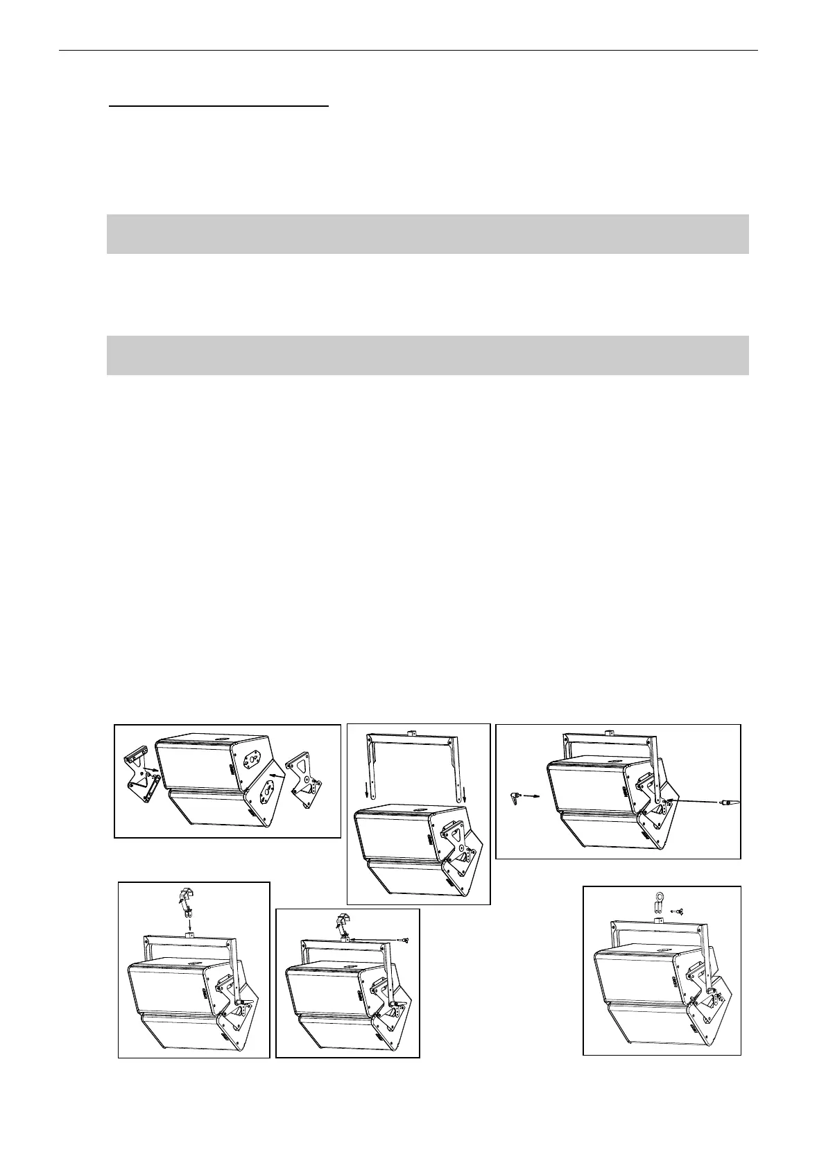
8.4.6 Two GEO S12 flown horizontally
Required items
1 x “U” Bracket for two GEO S12s (GPT-PSBRK)
1 x Lifting Ring (VNT-XHBRK)
Or 1 x Truss hook (VNT-TCBRK)
IMPORTANT
Ensure that suspension point is strong enough to hold two GEO S12s weight.
Procedure
Slide GPT-PSBRK side plates into GEO S12s connecting plate oblong holes;
Lock safety pins into GEO S12s connecting plate;
IMPORTANT
Ensure that safety pins are properly locked into GEO S12s connecting panels.
Adjust inter-cabinet angle and lock to required angle value with 8x20 quick release pins;
Position “U” bracket over these side plates; align centre holes;
Insert adjustment handles, adjust vertical angle and tight the handles to prevent GEO
S12s from rotating around “U” bracket;
Cable suspension:
Connect lifting ring VNT-XHBRK to “U” bracket by inserting 8x45 quick release pin
dedicated holes;
Ensure lifting ring is properly locked to “U” bracket;
Connect assembly to suspension point with sling and shackle (not provided).
Truss suspension
Connect truss hook VNT-TCBRK to “U” bracket by inserting 8x45 quick release pin in
dedicated holes;
Ensure truss hook is properly locked to “U” bracket;
Lift and position assembly, lock hook on truss suspension point and secure with hook
cable.