GEO S12 HARDWARE SETUP PROCEDURE Page 67/106
8.4.9 Ground stacked LS18 and GEO S1210
Required items
M pairs of rigging plates (LST-XBOW) for M x LS18
N Pairs of Rigging Plates (GPT-XBOW) for N x GEO S12;
1 ground stack device (GPT-GSTK);
4xN Quick release pins for N cabinets;
IMPORTANT
- Ground stack device GPT-GSTK is rated for a maximum of:
6xGEO S1210s or 2xLS18s + 4xGEO S1210s or 4xLS18s
in any inter cabinet angle configuration, provided this device is assembled according to
below rules.
- Ground stack device GPT-GSTK must always be installed on a horizontal surface;
- Bottom GEO S12 tilt angle must be limited to +/-10°
- Ensure that public is not allowed within a safety area which radius is equal or higher
than assembly height.
- It is highly recommended to secure the system to a fix point located at the back of the
stack.
Optional GPT-TLB link bar for GPT-XBOW
GPT-XBOWs are delivered with standard link bars which allow both stacked and flown setups. However,
these link bars require perfect alignment of angle setting holes when adding cabinets.
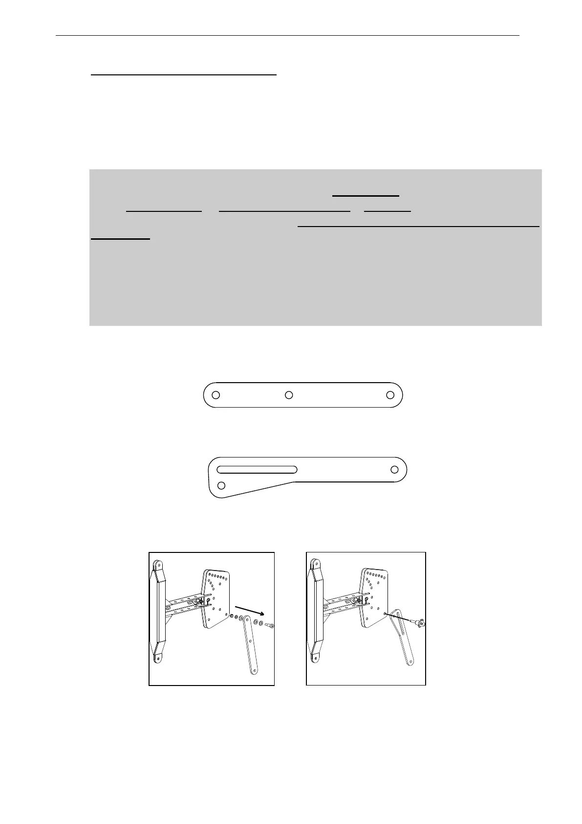
GPT- XBOW STANDARD LINK BAR
To facilitate flying and stacked operation, an optional link bar with oblong holes (GEOS12-TLB, pair of
link bars provided with two 8x20 quick release pin) is available in the GEO S12 accessory range.
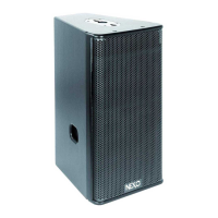
GPT-XBOW OPTIONAL GPT-TLB LINK BAR
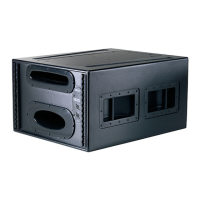
To install GPT-TLB, remove the standard link as well as nut, screw and washers.
When using GPT-XBOW for stacked setups, insert pins in the two circular holes.
REMOVING STANDARD LINK BAR INSERTING PINS - STACKED SETUPS