Page 40/106 GEO S12 HARDWARE SETUP PROCEDURE
8.3.5 LS18 & GEO S12 vertical array rigidly mounted on a ceiling
Required items
1 x GPI-BUMPER (allows +/-5° bumper tilt when installed below a flat surface; if higher
bumper tilt is required, surface will have to be defined accordingly) ;
(M-1) x GPI-ANPL1 for M x LS18
M x LSI-CPLA counter-plates for M x LS18
N x GPI-ANPL for a N x GEO S12 (ANPL1 ranges from 0.2° to 3.15°, ANPL2 ranges from
5° to 10°, ANPL3 ranges from 16° to 30°)
Four 12mm diameter screws (not provided)
IMPORTANT
Ensure that the ceiling is strong enough to hold 4 times LS18 & GEO S12 cluster weight
and that the four screws 12mm diameter and corresponding plugs required to fix the
bumper under the ceiling are properly dimensioned.
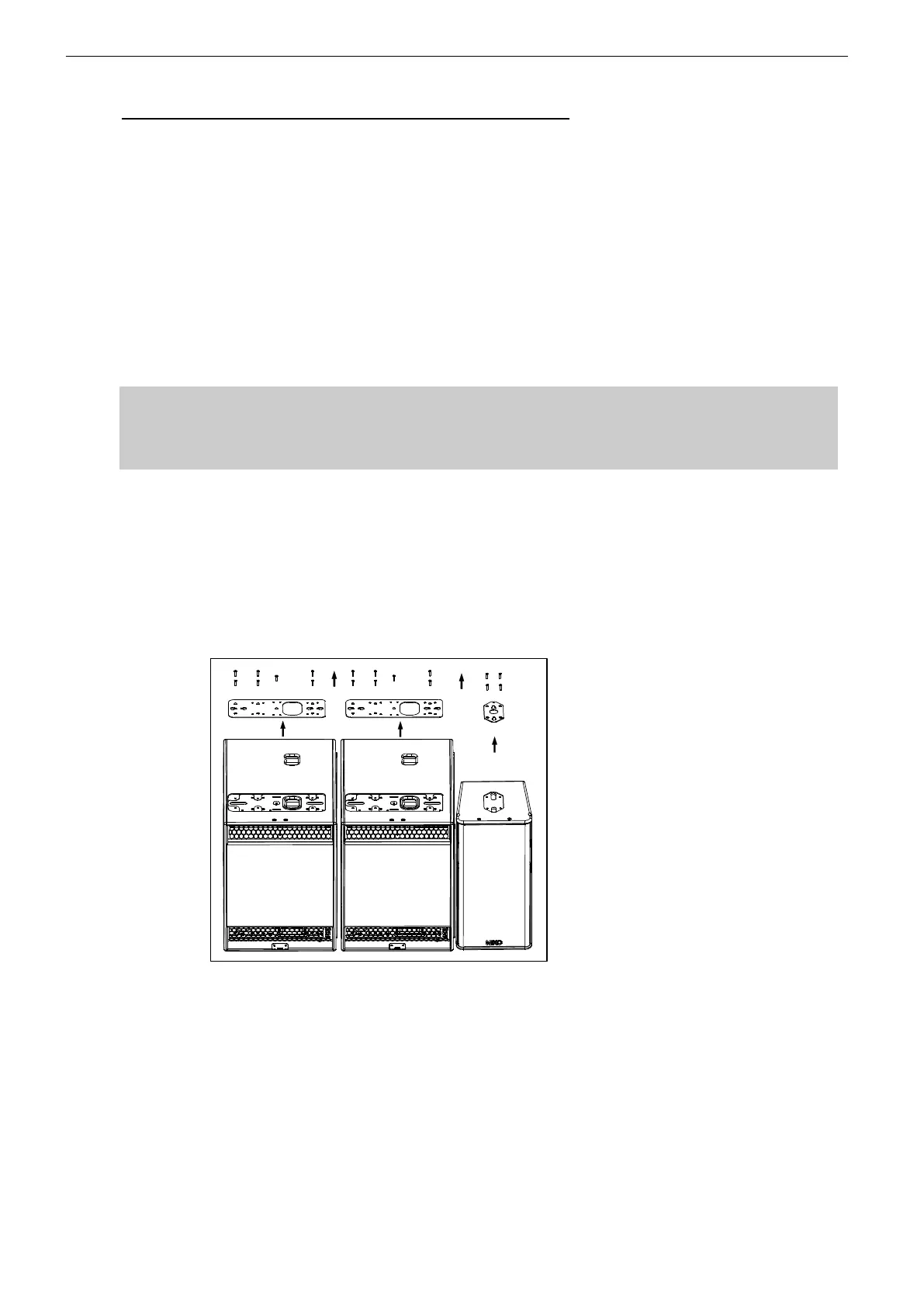
Procedure
(1) Set LS18s and GEO S12s sideways according to cluster configuration;
(2) Remove the TORX screws holding connector plates on upper side of all LS18s and
GEO S12s;
(3) Remove the connector plates from all LS18 and Geo S12s;
(4) Remove the 4 locking screws from LS18 side wood panel (see figure below), these
are no longer to be used;