GEO S12 HARDWARE SETUP PROCEDURE Page 41/106
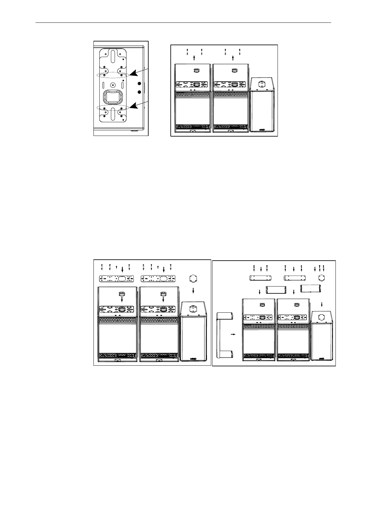
(5) Apply Loctite 243 or equivalent to the screws that attach the LS18 connector plate to
the cabinet, and reinstall the LS18 connector plates (see figure below left);
(6) Position Geo S12 bottom counter-plates (see figure below left);
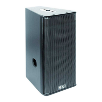
(7) Position GPI-ANPL1 angle plates (set at 0.2°) and LSI-CPLA top counter-plates on
LS18 upper sides according to figure below right;
(8) Position angle plates and top counter-plates from GPI-ANPL to required GEO S12
inter-cabinet angle value between GEO S12 upper sides according to figure below right;
(9) Use thread lock coated screws (if not apply Loctite 243 or equivalent to shoulder
screws) from LSI-CPLA and GPI-ANPL kits;
(10) Screw all shoulder screws so that all plates and cabinets are tightened together;
(11) Flip the cluster upside down to access connector plates located on the down side;
(12) Repeat all above steps from #2 to #10;
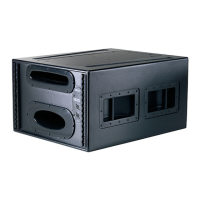
(13) Position the GPI-BUMPER bumper to required angle position and use the four
shoulder screws to connect it the bumper to the top cabinet;