GEO S12 HARDWARE SETUP PROCEDURE Page 37/106
8.3.4 GEO S12 vertical array rigidly mounted on a ceiling
Required items
1 x GPI-BUMPER (allows +/-5° bumper tilt when installed below a flat surface; if higher
bumper tilt is required, surface will have to be defined accordingly) ;
(N-1) x GPI-ANPL for a N x GEO S12 array (ANPL1 ranges from 0.2° to 3.15°, ANPL2
ranges from 5° to 10°, ANPL3 ranges from 16° to 30°)
Four 12mm diameter screws (not provided)
IMPORTANT
Ensure that the ceiling is strong enough to hold 4 times GEO S12 cluster weight and that
the four screws 12mm diameter and corresponding plugs required to fix the bumper
under the ceiling are properly dimensioned.
Procedure
(1) Set all GEO S12 sideways according to cluster configuration;
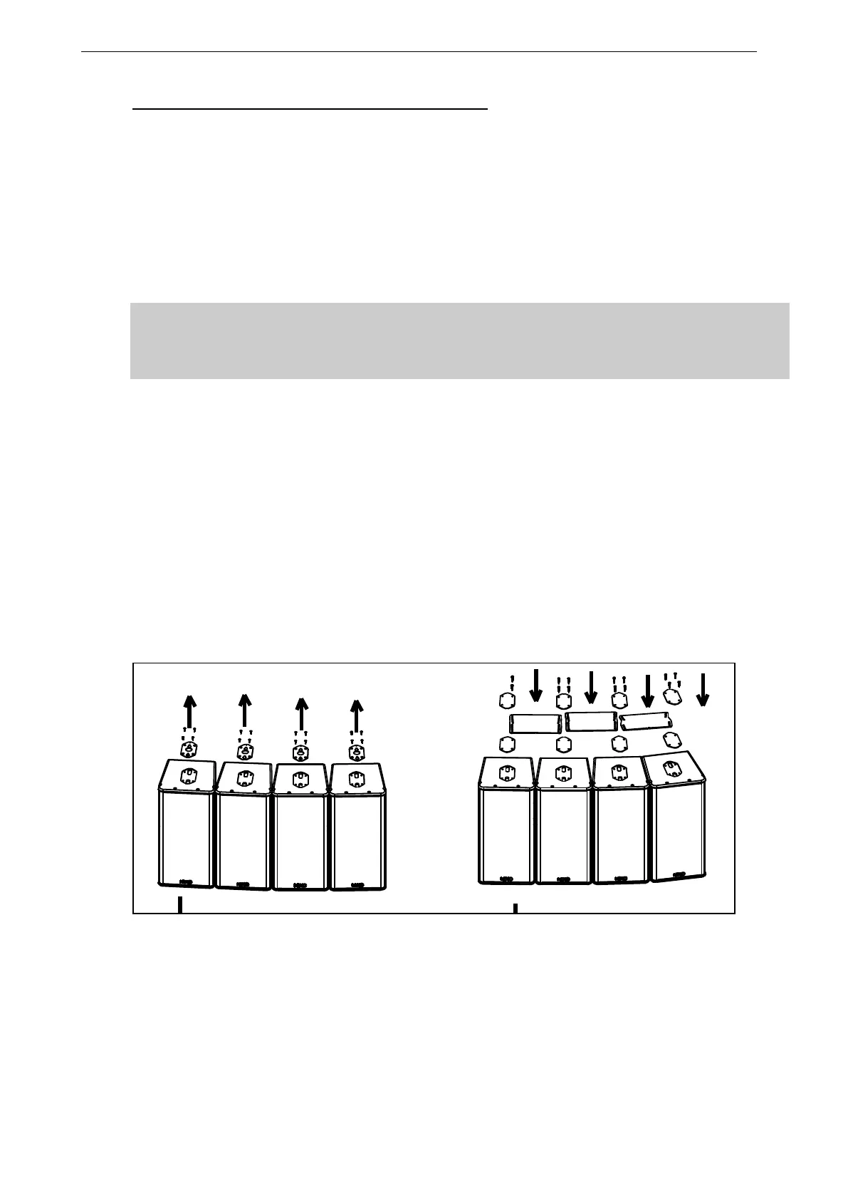
(2) Remove the four TORX screws holding connector plates on upper side of all GEO
S12’s;
(3) Remove the connector plates from all Geo S12’s;
(4) Position bottom counter-plates, angle plates and top counter-plates from GPI-ANPL
kit to required inter-cabinet angle value between cabinets upper sides;
(5) Use thread lock coated screws (or if not apply Loctite 243 or equivalent to shoulder
screws) from GPI-ANPL kits;
(6) Screw shoulder screws so that all plates and cabinets are tightened together;