STEP 8
S2 PHOTO
STOP
START
S1 EDGE
35
SET
RADI
STOP
36
Withthecontrolunitpoweredup(ifcontrolunitprotectionisnot
activated)theyellow“Set”ledflashesbrieflyand,ifeverythingis
correctlyhookedup,thered“S1 Edge”,“Stop”and“S2 Photo”
LEDsturnontoindicatethatthethreesafetycontactsareclosed
circuits.
Theyellow“Set”LEDisexclusivelyreservedforprogramming.
8.1 – IMPUT STATUS INDICATION LEDS
RED S1 EDGE LED:
- oninthefixedmodeiftheS1Edgecontact(terminals9-10)is
closed
- offiftheS1Edgecontact(terminals9-10)isopened
RED START LED:
- oninfixedmodeiftheStartcontact(terminals7-8)isclosed
- offiftheStartcontact(terminals7-8)isopened
WhenSTARTontheboardispressedoracontrolsignalissent
bywireandtheredLEDflashesthreetimeswithoutthesystem
executingthemanoeuvre,then“wireinputsareinlockmode”:
seepar.14.2(advancedprogrammingmanual).
RED STOP LED:
-oninfixedmodeiftheStopcontact(terminals6-8)isclosed
-offiftheStopcontact(terminals6-8)isopened
RED S2 PHOTO LED:
-on in fixed mode if the S2 Photo contact (terminals 4-8) is
closed
-offiftheS2Photocontact(terminals4-8)isopened
YELLOW SET LED:
-is on in fixed mode or flashes when the control unit is in a
programming menu
-isoffwhenthecontrolunitisinoutofaprogrammingmenu
LED INDICATIONS
RED RADIO LED:
- flashes when a command is received through King Gates
transmitter
-is on in fixed mode when the control unit is in a radio
programming menu
-isoffwhenthecontrolunitisinstandbymode
RED ERROR LED:
- seeparagraph8.2
RED START LED, RED RADIO LED AND YELLOW SET LED:
- If, when attempting to enter any programming scheme, the
“Set”,“Radio”and“Error”LEDsflashfastthreetimes,itmeans
that the “controlunit protection”is activated. See Paragraph
10.3.1forsolvingtheproblem.
8.2 – ERROR STATUS LED
RED “ERROR” LED:
Thered“error”LEDhastwofunctions:
- During automation’s movement, the LED flashes when a
mechanical stress point is detected (this corresponds to
increased motor effort). Adjust FORCE and OBS knobs
(slightly turn them clockwise) to solve this and check
gate mechanics if necessary. Attention: a minimum flash
of this LED during the door movement can be considered
as normal.
- Instandbymode,theLEDsshowsthecurrenterrortypewitha
seriesofregularflashesaccordingtothefollowingscheme:
Number of
ashes per
series
Error description
1 On-boardmemoryfault.
2
Photo-testofsafetydevicesfailed.See
Paragraph4.1forsolvingtheproblem.
3
Automation’s movement programming
required.Seestep6.
4
Input“S1Edge”setasaresistiveedgeand
checkfailed.SeeParagraph13.4forsolving
theproblem.
5 Powerlimitthreshold
6 Obstacledetectionduetoencoder
7 Obstacledetectionduetocurrent
8 Motornotconnected
3 Filloutthedeclarationofconformityanddeliverittotheowner
oftheautomationsystem;forthispurposeyoucanuseAnnex2
“CEDeclarationofConformity”.
4 Preparetheoperatingguideanddeliverittotheownerofthe
automationsystem;Annex1“OPERATINGGUIDE”canbeused
asanexample.
5 Preparethemaintenancescheduleanddeliverittotheowner
oftheautomationsystem;itmustprovidedirectionsregardingthe
maintenanceofalltheautomationdevices.
6 Postapermanentlabelorsigndetailingtheoperationsforthe
releaseandmanualmanoeuvre(usetheguresinAnnex1“Oper-
atingguide”).
7Beforecommissioningtheautomationsystem,informtheown-
erregardingdangersandhazardsthatarestillexisting.
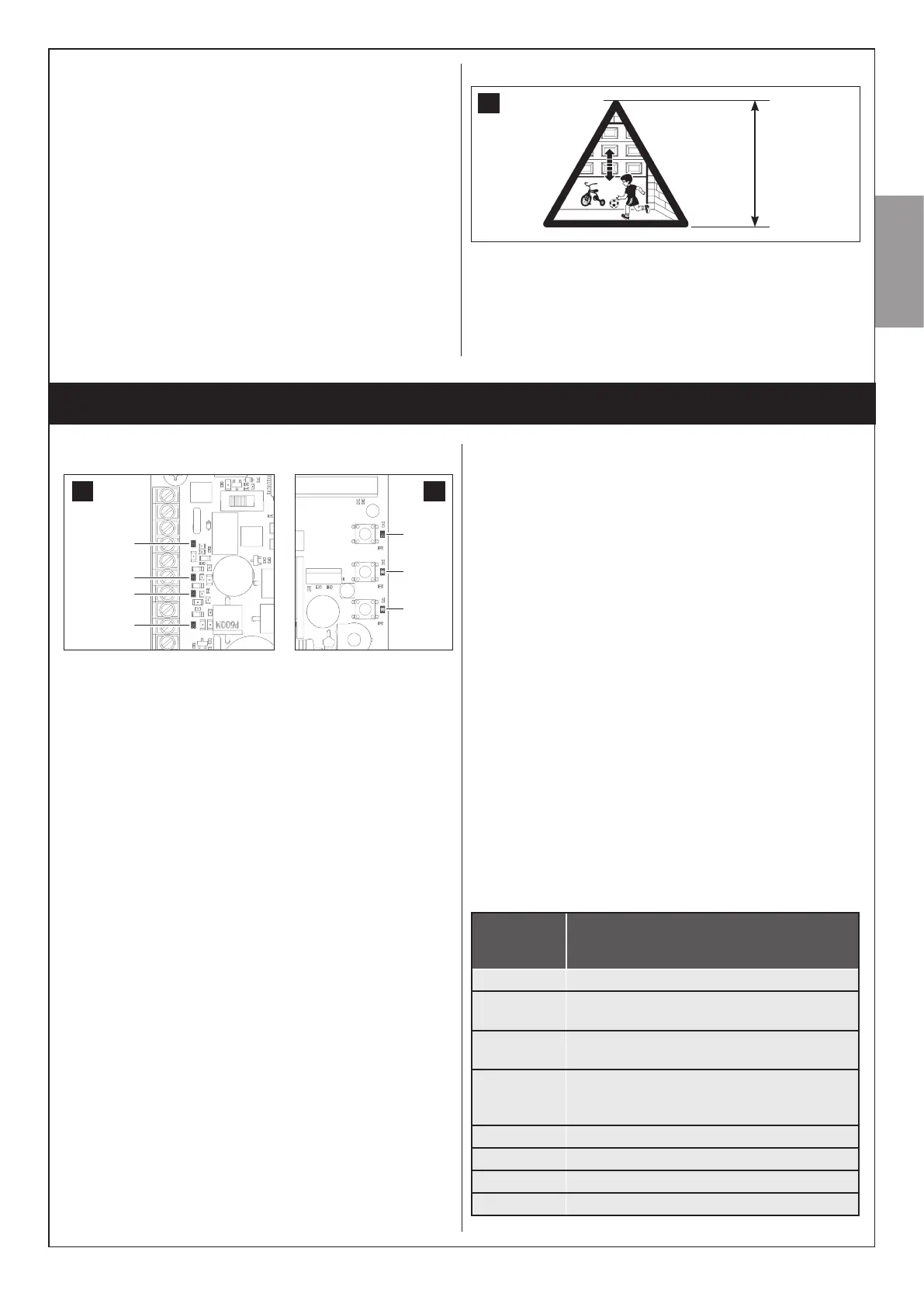
8 Postapermanentlabelorsignwiththisimageonthedoor
(minimumheight60mm)withinscriptionWARNING–RISKOF
CRUSHING.
34
min. 60 mm
English–19
English