EN
English – 11
A
B
C
D
1 2 3 4
9
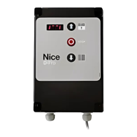
TABLE 5A - Push button panel board
Tag Description
A
Flat-cable connector for communication between push button panel
and control unit
B
DIP switches for changing control unit parameters and programming
(see table below for various congurations)
C
Rear buttons for selecting control unit programming
D
Connector for external emergency button.
Bridge if not in use
TABLE 5B - Display Board - Use of Dip Switches
DIP switch Description
1 ON
ON
1 2 3 4
OFF
ON
1 2 3 4
OFF
ON
1 2 3 4
OFF
ON
1 2 3 4
OFF
ON
1 2 3 4
OFF
ON
1 2 3 4
OFF
ON
1 2 3 4
OFF
Access type “P” parameters
(see p. 20).
• Use the rear buttons
C
to
scroll through the parameters;
• To change the parameters, raise
DIP switch 4 to the desired
parameter and use the rear
buttons
C
to change the
value.
2 ON
ON
1 2 3 4
OFF
ON
1 2 3 4
OFF
ON
1 2 3 4
OFF
ON
1 2 3 4
OFF
ON
1 2 3 4
OFF
ON
1 2 3 4
OFF
Access type “C” parameters
(see table on p. 27).
• Use the rear buttons
C
to
scroll through the parameters;
• To change the parameters, raise
DIP switch 4 to the desired
parameter and use the rear
buttons
C
to change the value.
1 and 2 ON
ON
1 2 3 4
OFF
ON
1 2 3 4
OFF
ON
1 2 3 4
OFF
ON
1 2 3 4
OFF
ON
1 2 3 4
OFF
Access type “U” parameters
(see table on p. 26).
• Use the rear buttons
C
to
scroll through the parameters;
• To change the parameters, raise
DIP switch 4 to the desired
parameter and use the rear
buttons
C
to change the value.
These parameters will only be
visible if deletions other than EE_0
have been made.
3 ON
ON
1 2 3 4
OFF
ON
1 2 3 4
OFF
ON
1 2 3 4
OFF
ON
1 2 3 4
OFF
ON
1 2 3 4
OFF
ON
1 2 3 4
OFF
ON
1 2 3 4
OFF
Position ne adjustment (2
encoder increments at a time)
See “3.12.1. Position fine
adjustment” on p. 16
1,2 and 3 ON
ON
1 2 3 4
OFF
ON
1 2 3 4
OFF
ON
1 2 3 4
OFF
ON
1 2 3 4
OFF
ON
1 2 3 4
OFF
ON
1 2 3 4
OFF
ON
1 2 3 4
OFF
Clear internal memory with control
unit reset, essential for inverter
initialisation.
See par. “3.11 Deleting the
control unit memory“on page
14
4 ON
ON
1 2 3 4
OFF
ON
1 2 3 4
OFF
ON
1 2 3 4
OFF
ON
1 2 3 4
OFF
ON
1 2 3 4
OFF
ON
Set opening, closing and partial-
opening positions.
See par. “3.12 Position learning”
on page 15
3 and 4 ON
ON
1 2 3 4
OFF
ON
1 2 3 4
OFF
ON
1 2 3 4
OFF
ON
1 2 3 4
OFF
ON
1 2 3 4
OFF
ON
1 2 3 4
OFF
ON
Change the direction of rotation of
the motor.
Parameter P75 can also be used.
See “3.13 Changing direction of
motor rotation” on p. 17
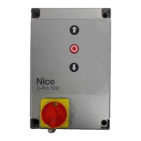
2.7 Description of push button panel board
Front
Back