- A ・ -
VBA18001-R.3719.A
logo�Q0440�forGraphic
070518�Gdesign�ito
(1) Gain difference adjustment among Channels
Camera is faced to the color viewer (LV13 equiv.) with ND lter (-4 steps) being put between them. Change the
adjustment gain value to even out variation among channels.
However, when the below PCB(s) is/(are) replaced, follow each instruction before this and subsequent
adjustment.
・
When the DG-PCB is replaced:
Input the serial number of the body.
・
When the DG-PCB or image-PCB is replaced:
With the QR barcode reader, read the bracket number of the image-PCB, and write the corresponding data into
the DG-PCB. The data will be added every two weeks (e.g. "D3_0001.csv", "D3_0002.csv"...; "0001", "0002"
means le number).
(2) Stitching adjustment
When the image pickup device is created, the stepper performs multi-zone exposure to create it, and this
adjustment is made so as to even up a difference among zones. Using the shutter tester (L12), the adjustment is
made with the tool lenses (F1.4 and F8).
(3) Sensitivity adjustment
Under condition of ISO200 and ISO800, the camera is faced to the color viewer (LV13 equiv.) with ND lter (-6
steps) being put between them. Using the tool lens (F5.6), the adjustment is made by changing the ampgain so
that G output can fall in the standard range. The gain value is adjusted so that the G output average value (Average
of Gr/Gb) of (425×425 pixels), which was deviated from the center by 425 pixels, can reach the target output
level. By this sensitivity adjustment, the gain difference adjustment among channels is automatically made.
Next, under condition of ISO6400, the camera is faced to the color viewer (LV13 equiv.) with ND lter (-8
steps) being put between them. Using the tool lens (F5.6), perform the same adjustment as the above.
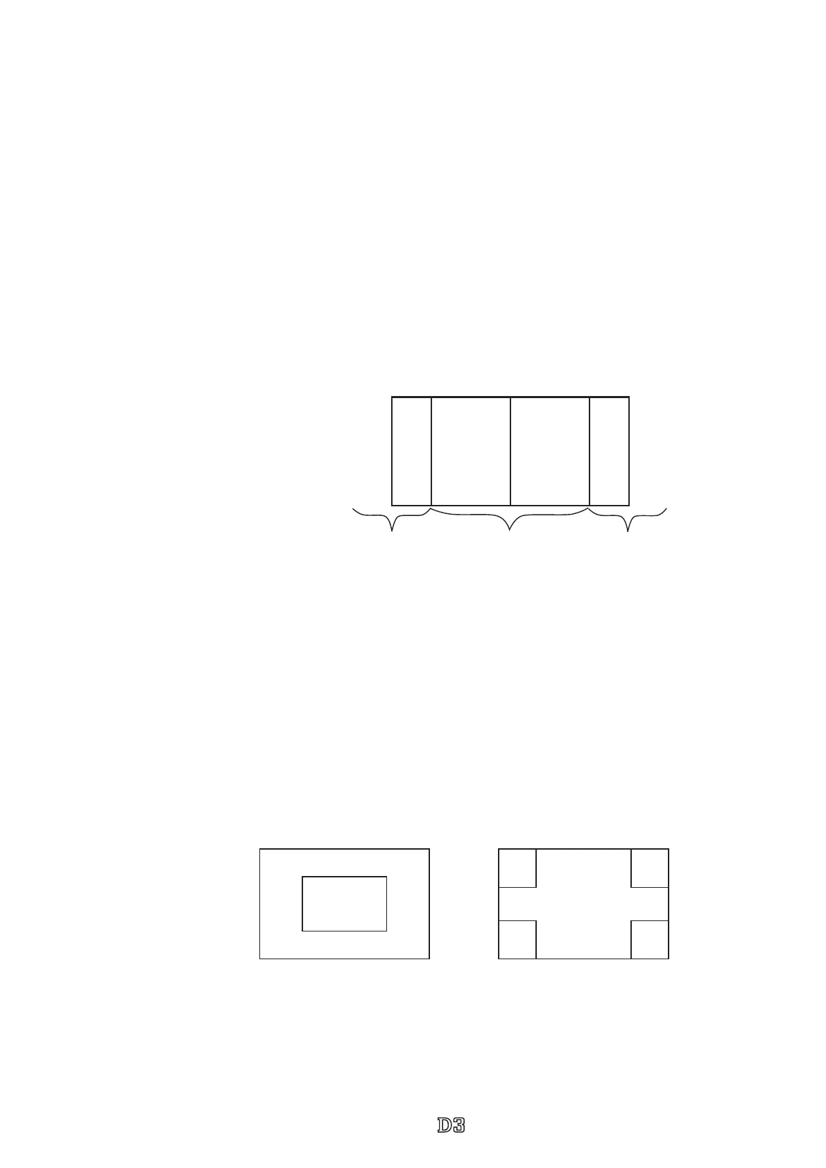
(4) Shading adjustment
Using the shutter tester (LV12) and the tool lens (F8), the adjustment of white balance distribution is made for 3
areas [Area ① : Central 2128×1416-pixel area; Area ② : All the divided areas except ③ -areas after dividing
(4266×2842-pixels) into (29×25-pixels); Area ③ ; 4 corners of (4×6-pixels) after dividing (4266×2842-pixel)
into (29×25-pixels)].
(5) Gr/Gb compensation adjustment (R/B lter) - Line crawl adjustment
Using the tool lens (F5/6), the camera is faced to the color viewer (LV13 equiv.) with SP3 (R lter) or SP1 (B
lter) being put between them, and the adjustment is made so that the difference in G output average between
B-G line and G-R line when the whole screen is divided in areas, can fall in the standard range.
Area
①
Area
②
Area
③
Area
④
① ② ③
Area
③
4×6
Area
②
29×25
Area
③
4×6
Area
③
4×6
Area
③
4×6
Area
①
2128×1416
 Loading...