Chapter 5 Laser Unit
5.3 C-LU3EX Three-laser Unit EX
1-153
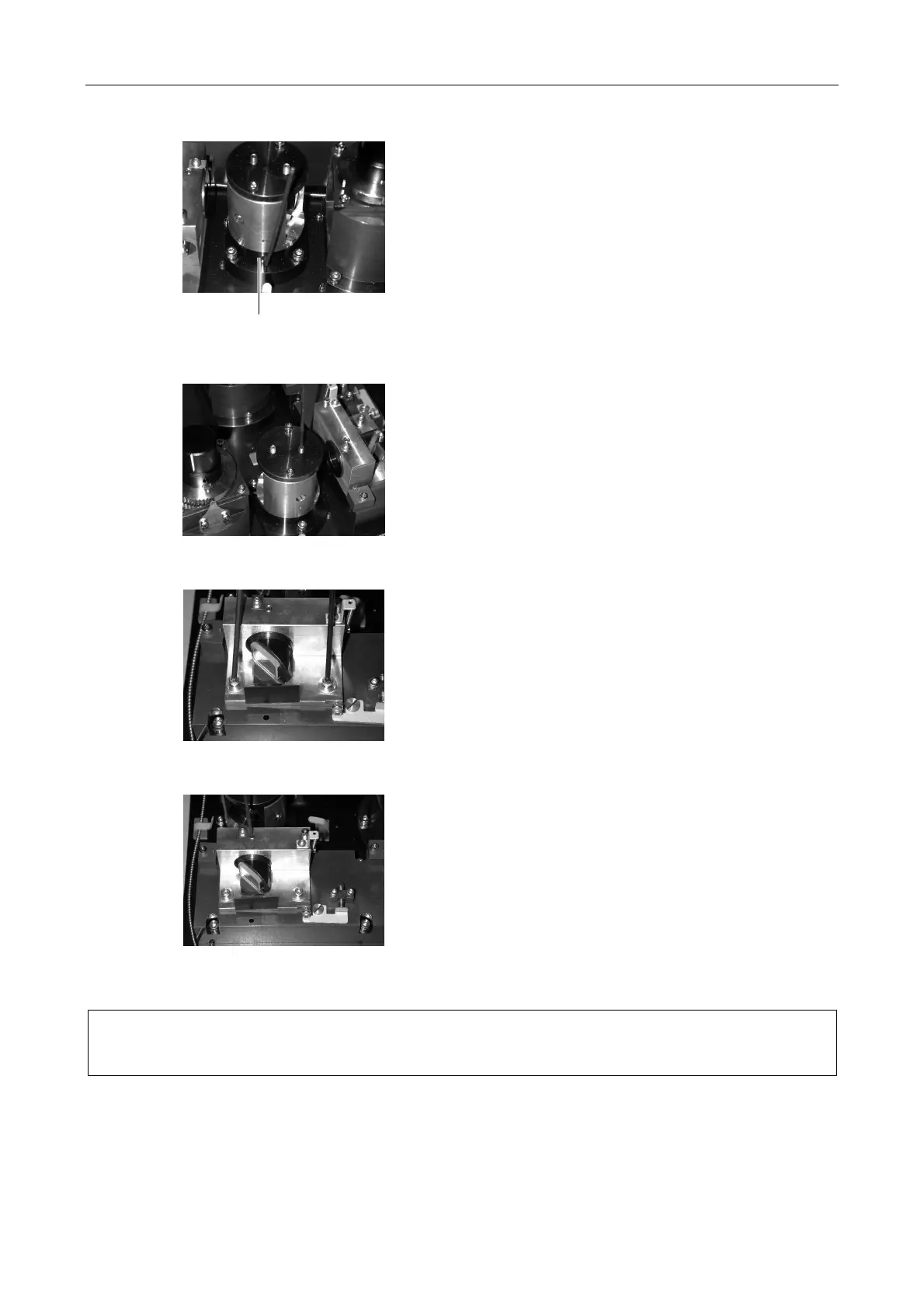
Figure 5.3-74
Figure 5.3-75
4. Carefully tighten the beam shift unit vertical axis
clamp screw. Readjust the rotation axis on the beam
shift unit if the brightness decreases here. Then
carefully tighten the horizontal axis clamp screw.
Figure 5.3-76
Figure 5.3-77
5. Once the point giving a maximum brightness has
been found, carefully tighten the two horizontal axis
clamp screws alternately on the dichroic mirror
adjustment unit. If the brightness decreases after
tightening, readjust the vertical axis.
6. Carefully tighten the vertical axis clamp screw.
Excessive tightening is not necessary if large
tightening deviations occur.
7. Record the brightness for each laser.
8. Close all the laser shutters.
• When the AOM unit will not be used, proceed to Section 5.3.8, “Attaching the Sheet Metal
Cover.”
• To use the AOM unit, continue to Section 5.3.7, “Adjusting the AOM Controller.”
Horizontal axis clamp screw