Chapter 5 Laser Unit
5.4 LU4A Four-laser Module A
1-162
2
405(440)-nm laser installation and 638-nm laser installation
1. Remove six hexagonal bolts (three bolts each) at the L2 position and L1 position of the four-laser
module A for the 405-nm (440-nm) laser and 638-nm laser.
Figure 5.4-16
2. Mount the 405(440)-nm laser to the L2 position of
the four-laser module A. And then mount the 638-nm
laser to the L1 position on the laser unit. The laser
emission port must contact the black ring to prevent
scattered light of laser from leaking. Press the laser
emission port against the black ring. The black ring
becomes flattened. Fix the laser body temporarily
with four hexagonal bolts of step 1.
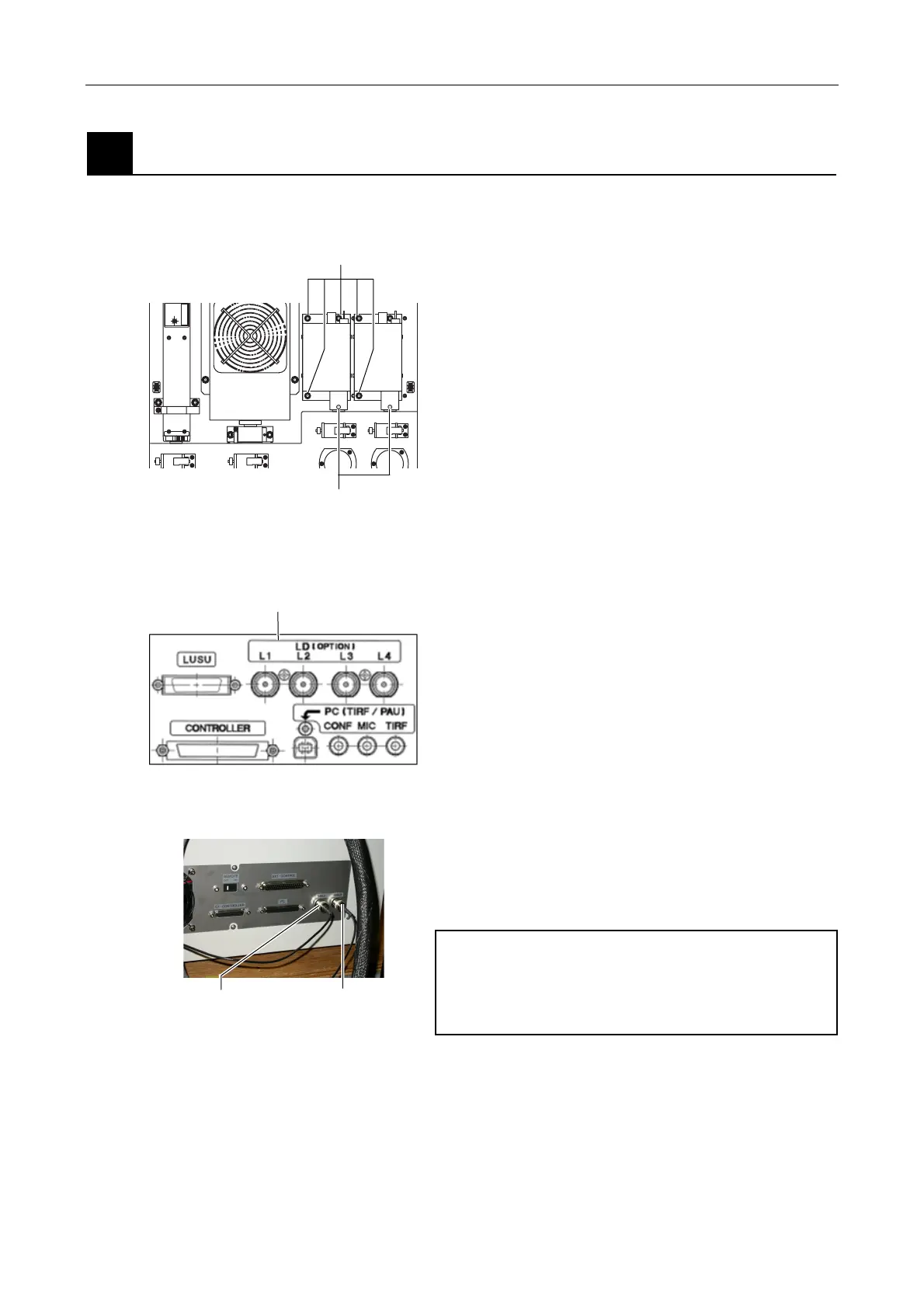
(Connectors on the four-laser module A rear panel)
Figure 5.4-17
3. < for LU4A >
Do not connect the modulation cable. If connected,
the device does not operate correctly.
<for LU4> (Do not use in this system.)
Connect the modulation cable of the 405-nm laser to
the "405 LD" connector. And connect the modulation
cable of the 638-nm laser to the "638 LD" laser
connector.
CAUTION:
Put on laser-protection goggles in 405LD
adjustment.
(E.g.: Yamamoto Kogaku 1/100-attenuation Blue Laser
Diode YL331M)
Figure 5.4-18
Attach while pressing against the
black ring just enough to compress it.
Fix with hexagonal bolts
Do not connect a cable to these LD connectors.
405LD connector 638LD connector