Chapter 5 Laser Unit
5.4 LU4A Four-laser Module A
1-193
5
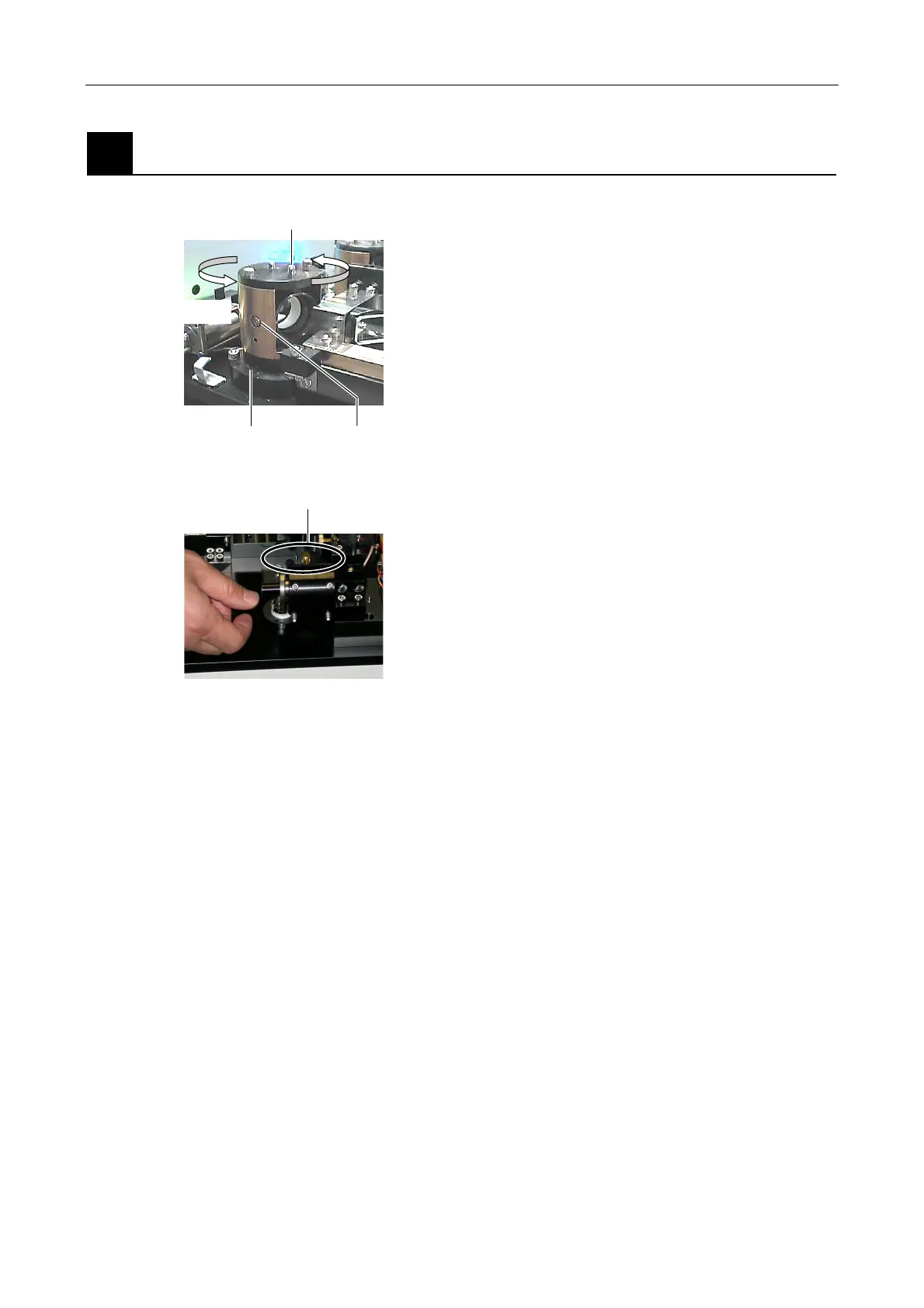
Fixing the beam shift part and the optical fiber coupling device
Figure 5.4-103
1. Tighten the clamp screws for the horizontal direction
and the vertical direction to fix the L3 beam shift part.
Figure 5.4-104
2. Tighten the center knurled screw of the optical fiber
coupling device. And then, gradually tighten two
other knurled screws to fix the optical fiber coupling
device.
Rotate by hand
Vertical clamp screw
(nearer to the axis A)
Axis A Horizontal clamp screw
Knurled screws