Chapter 5 Laser Unit
5.4 LU4A Four-laser Module A
1-195
Figure 5.4-107
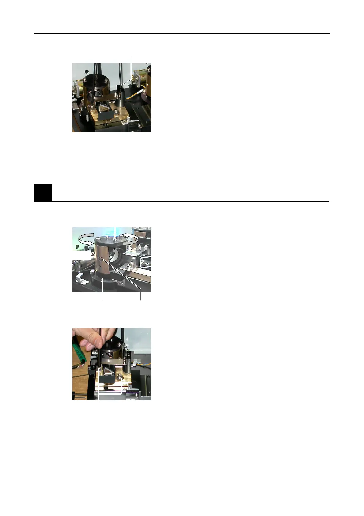
6. Rotate the setscrew for the adjustment in the vertical
direction on the L4 dichroic mirror adjustment part
and adjust the angle to reach the maximum intensity
of the laser light.
7. Repeat Step 3 to Step 6 to maximize the laser intensity.
8. Repeat Step 1 to Step 7 for the 405-nm laser and the 605-nm laser.
2
Fixing the beam shift part and the optical fiber coupling device
Figure 5.4-108
1. Tighten the clamp screws for the horizontal direction
and the vertical direction to fix the L1 beam shift part,
L2 beam shift part, and L4 beam shift part.
Figure 5.4-109
2. Tighten the clamp screws for the horizontal direction
and the vertical direction to fix the L1 dichroic mirror
adjustment part, L2 dichroic mirror adjustment part,
and L4 dichroic mirror adjustment part.
3. Record the power of each laser.
Vertical setscrew
Rotate by hand
Vertical clamp screw
(nearer to the axis A)
Axis A Horizontal clamp screw
Clamp screw