Chapter 4 Setting Up the Microscope
4.2 Setup Procedure
1-78
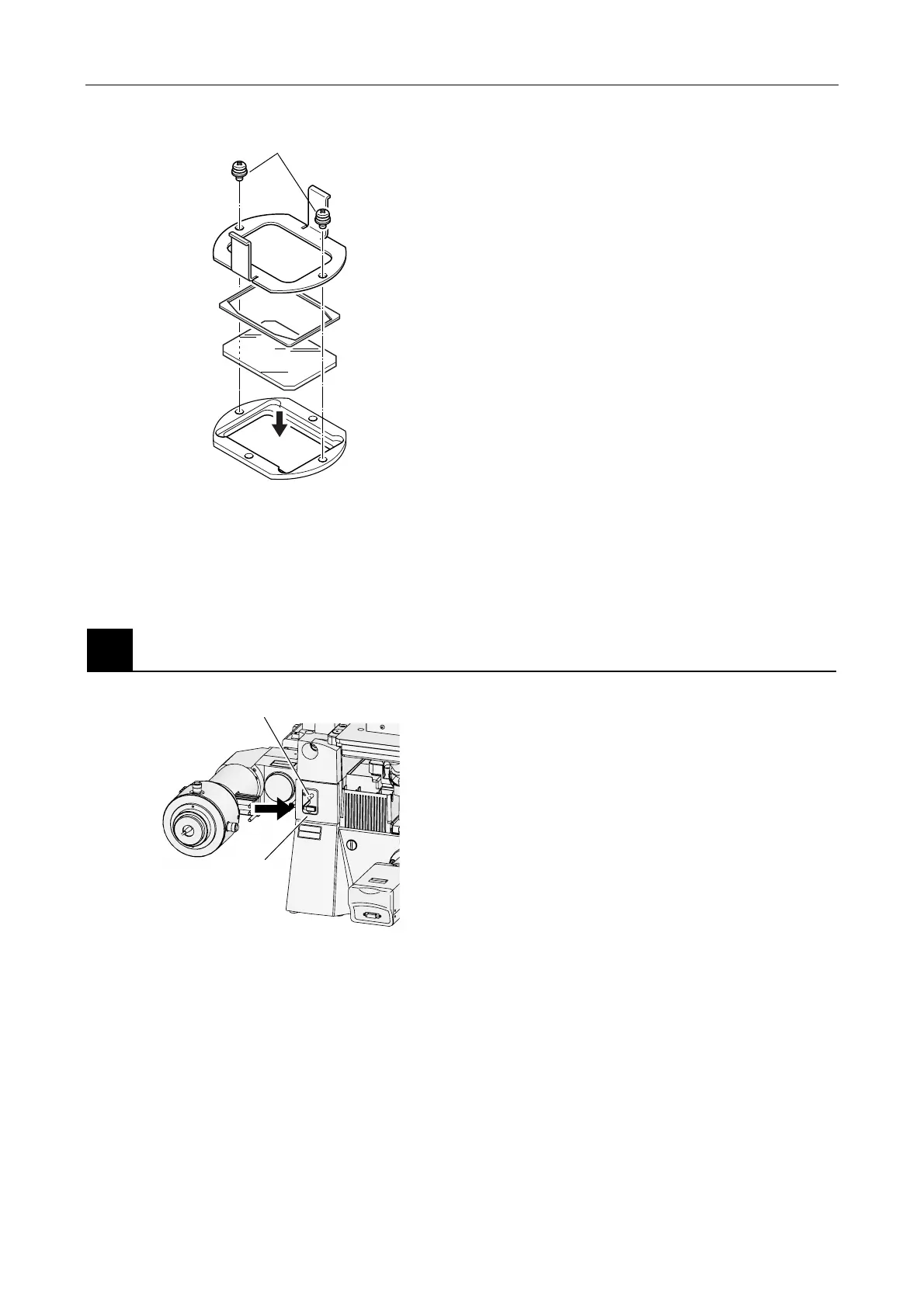
2. Remove the mirror unit from inside the
illuminator, and insert the dichroic mirror.
(1) When removing the mirror unit, pull out the
mirror switch lever, and then pull out the
mirror unit while holding the tab of the mirror
unit (magnetic lock).
(2) Remove the two holder plate locking
screws. Next, remove the holder plate and
flat spring to attach the mirror.
• Mirror size: 36 x 25.7 x 1
Mirror unit
Figure 4.2-9
3. Attach the mirror unit in its original position, and
then close the cap of the mirror replacement
opening.
(1) There is a positioning hole on the mirror
unit. Securely attach the mirror unit to the
illuminator to fit the pin on the main body.
(2) Screw the cap of the mirror replacement
opening until it is closed.
(3) Tighten the optical path switching module
screw using the Allen wrench, and secure
the cover.
3
Attach the field diaphragm unit.
C
A
U
T
IO
N
–
C
L
A
S
S
3
B
L
A
S
E
R
R
A
D
IA
T
IO
N
W
H
E
N
O
P
E
N
A
V
O
ID
E
X
P
O
S
U
R
E
T
O
T
H
E
B
E
A
M
V
O
R
S
IC
H
T
–
L
A
S
E
R
S
T
R
A
H
L
U
N
G
K
L
A
S
S
E
3
B
,
W
E
N
N
A
B
D
E
C
K
U
N
G
G
E
Ö
F
F
N
E
T
N
I
C
H
T
D
E
M
S
T
R
A
H
L
A
U
S
S
E
T
Z
E
N
Figure 4.2-10
1. Remove the rubber cap on the left side of the
microscope.
2. Insert the field diaphragm unit.
3. Tighten the locking screw using an Allen wrench,
and secure the field diaphragm unit.
Holder plate locking screws
Holder plate
Flat spring
Mirror
(Place the
reflection
surface
downward.)
Field diaphragm unit
Locking scre