24 - Electrical System 41Service Manual – SC250, Scrubtec 334, MA 30
24 - Electrical System
Functional Description
The machine electrical system is composed of the following components:
• Lithium battery: the battery pack contains the
lithium cell protection system (Battery Manage-
ment System) and provides power (36Vdc nominal
voltage) to the machine system only after an ac-
tivation system is provided by the machine start
push-button located on the Main control board
(EB2). Voltage from the battery can therefore only
be directly measured at the battery connector dur-
ing machine operation. The battery connector also
contains the signal outputs necessary to display
the battery charge level on the machine control
panel. Any error codes from the battery manage-
ment system (BMS) are displayed exclusively via
the yellow and red LEDs on the battery, which can
be activated by pressing the push-button next to
the LEDs themselves.
• Main machine controller (EB1): it receives the
controls from the Main control board (EB2) and
provides power directly to all machine components
(motors, pump, solution sensor). It also receives
the battery charge level signals which are trans-
mitted to the controller to be displayed.
• Main control board (EB2): this is fully responsible
for the user interface, as it contains all control
push-buttons and the indicator LEDs, and is con-
nected to the 2 operator presence sensors on the
handlebars. All information from and for the user
is exchanged with the Main machine controller
(EB1) via I2C protocol.
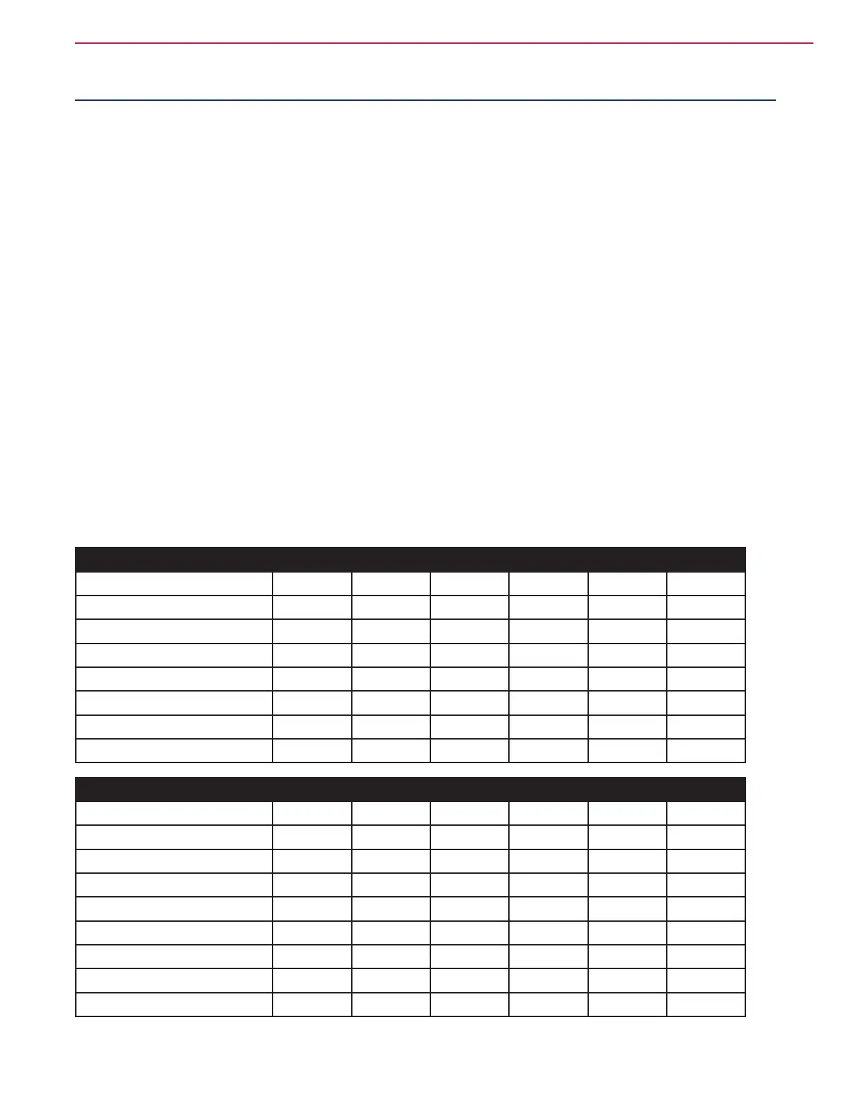
LED Operation on Main Control Board
DISPLAY DURING DISCHARGE (machine operation)
Battery level (approximated ±5%) LD1 LD2 LD3 LD4 LD5 LD6
>90% On On On On On On
75% - 90% On On On On On
60% - 75% On On On On
45% - 60% On On On
30% - 45% On On
15% - 30% On
0% - 15% Flash
DISPLAY DURING CHARGE (charger output connected to CHARGE.1,2)
Battery level (approximated ±5%) LD1 LD2 LD3 LD4 LD5 LD6
0% - 15% Flash
15% - 30% On
30% - 45% Flash On
45% - 60% Flash Flash On
60% - 75% Flash Flash Flash On
75% - 90% Flash Flash Flash Flash On
>90% Flash Flash Flash Flash Flash On
Charge completed On
 Loading...


