30 - Solution System 51Service Manual – SC250, Scrubtec 334, MA 30
30 - Solution System
Functional Description
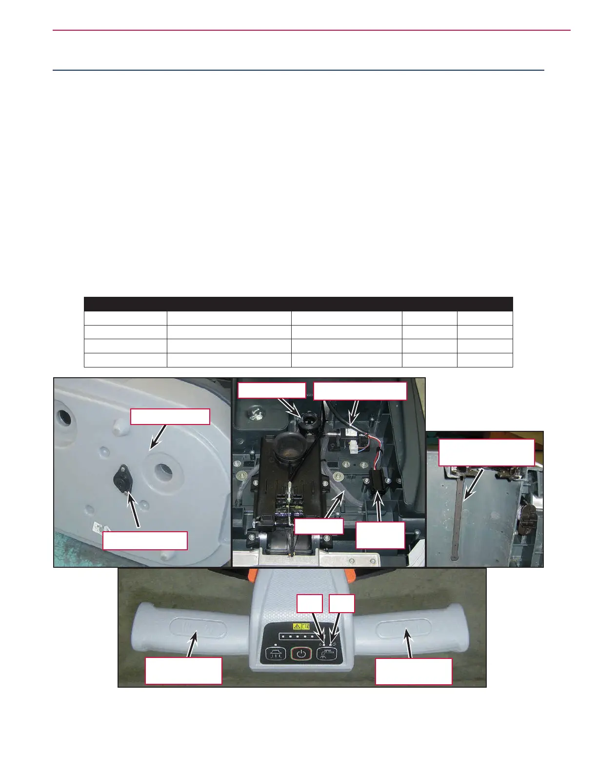
The solution system supplies detergent to the brush when cleaning the oor. The solution tank is also part
of the machine recovery tank. The solution ows from the tank to the valve before reaching the lter and the
water pump (PM), and then to the solution dispensers in the brush compartment area.
The system also includes a water sensor (S3) which warns the operator when the solution tank is empty via
the two washing push-button LEDs.
Solution ow levels 1 and 2 regulate the ow of solution to meet requirements.
If the water sensor (S3) does not detect water inside the hose within 10 seconds of the pump starting up, the
pump is stopped and the fault is indicated by the 2 solution ow LEDs (LD8, LD9) ashing alternately.
To re-activate the pump, just take both hands off the handlebars to deactivate the operator presence sensors
(S1, S2), then reactivate them.
The pump operates only with the following inputs/conditions:
• Brush function on
• At least one of the two handlebar sensors activated
• Sufcient battery charge level: at least one LED on ashing.
Water Flow
Flow rate set Square pulse Ton (+24V) Square pulse Toff LD8 LD9
1 (default) 18ms 36ms On Off
2 10ms 18ms On On
0 0ms - Off Off
Tank valve
Solution tank
Solution dispensers
Water pump (PM)
Filter
Hoses
Water
sensor (S3)
LD9LD8
RH hand presence
sensor (S1)
LH hand presence
sensor (S2)
 Loading...


