40 - Recovery System 85Service Manual – SC250, Scrubtec 334, MA 30
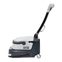
40 - Recovery System
Functional Description
The recovery water system removes the dirty water
from the oor and pipes it to a recovery tank. When
the machine is running, the dirty water on the oor is
collected by the squeegees assembly, and is directed
through the slots in the blades into the vacuum duct
and into the tank by the airow created by vacuum
system motor (M2).
The recovery tank is also part of the solution tank.
The collected dirty water is piped through two sleeves
into the recovery tank, while the airow continues to
the vacuum fan.
The automatic oat in the vacuum grid on the cover
stops the vacuum system motor (M2) from collecting
any liquid.
When the automatic oat closes and stops the vacuum
system, the vacuum system motor noise will increase
and the oor will not be dried.
The gasket on the input of the vacuum system motor
allows full functionality of the system, while the lter
built in the gasket prevents the passage of dirt and
debris.
The recovery water system is activated when the ma-
chine is switched on, and can be disabled or re-en-
abled by pressing the corresponding vacuum system
push-button
.
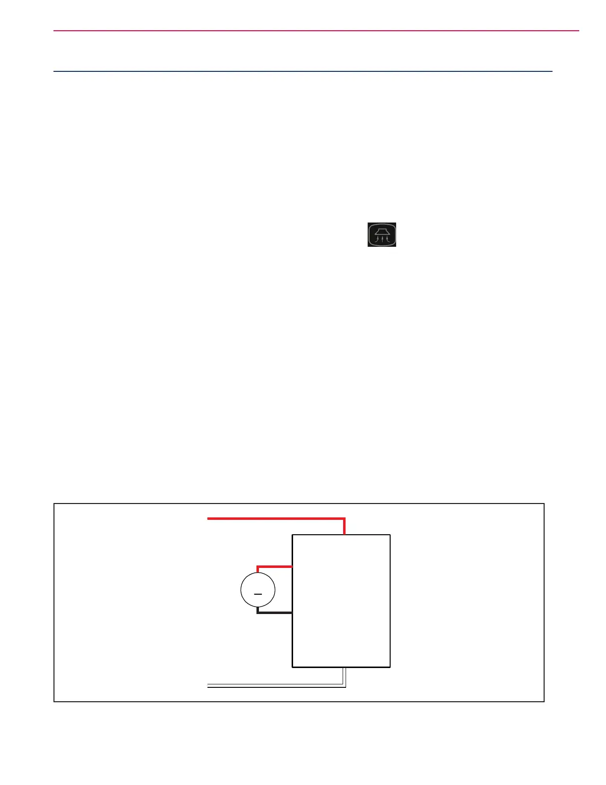
Wiring Diagram
VACUUM SYSTEM
MOTOR (M2)
M2
BATTERY+
BATTERY-
OUT2.+ Vacuum system motor output
OUT2.- Vacuum system motor output
MAIN MACHINE
CONTROLLER (EB1)
Figure 1
 Loading...


