Electrical System 81Service Manual – SC6500
™
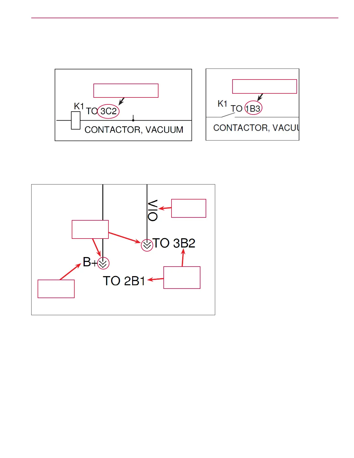
Typically relays (and contactors) are “split up” so that the relay winding is separated from the contacts.
The “control” side of the relay is shown in one location and the “load” side of the relay is shown in another
location. The two pieces may or may not be on the same page. The location of the contacts is described next
to the winding and vice versa.
Sometimes a circuit line is interrupted and is continued on another sheet or another location on the same
sheet. When this occurs you will need to match two termination points. At each termination point you will
see a “continued” symbol. Near the symbol the circuit will be identied by a wire color, a description of the
circuit or a unique letter. The circuit identication must be used to match the mating termination point.
There is also an address of where to nd the mating termination point. See examples below.
“Continued”
Symbols
Circuit
Description
Identification
Wire Color
Identification
Address
of mating
termination
point
To nd a connector that plugs into a component, see the Component Locations section to locate the
component then follow the wire lead (if there is one) to the connector. If you need more detailed information
about what a multi-pin connector looks like and where the wires are located in the connector, see the
Connector Pin-Outs section.
K1 Winding shown on Sheet 1 K1 Contacts shown on Sheet 3
Address of K1 winding
Address of K1 contacts
 Loading...