Recovery System 92Service Manual – SC6500
™
Circuit Description
Vacuum Motors M5 and M6 get positive voltage from the Battery when the load sides of contactors K5 and K1
are closed. Contactors K5 and K1 close when the A2 Control Board Assembly connects the K5 and K1 contactor
coils to battery ground. Vacuum Motors M5 and M6 are connected directly to battery ground.
The A2 Control Board Assembly connects the K5 and K1 contactor coils to battery ground when:
• The A3 Switch/Display Panel Assembly sends the A2 Control Board Assembly a signal via the CAN BUS that
the vacuum system has been switched on, or,
• The A1 Speed Controller sends the A2 Control Board Assembly a signal that the wheel drive is switched on,
the scrub system is enabled and the vacuum system has not been switched off.
Note: The A2 Control Board Assembly monitors the voltage input from the Vacuum Motor Shunt
wire connected to the ground side of Vacuum Motors M5 and M6. If the voltage is out of the
acceptable range (.07 - .12 volts for a single vacuum motor or .15 - .24 volts for dual vacuum
motors), the A2 Control Board Assembly will sense that the oat ball is sealed against the oat
cage and that the recovery tank is full. The A2 Control Board Assembly will then shut down
the vacuum and scrub systems and display a recovery tank full icon on the LCD.
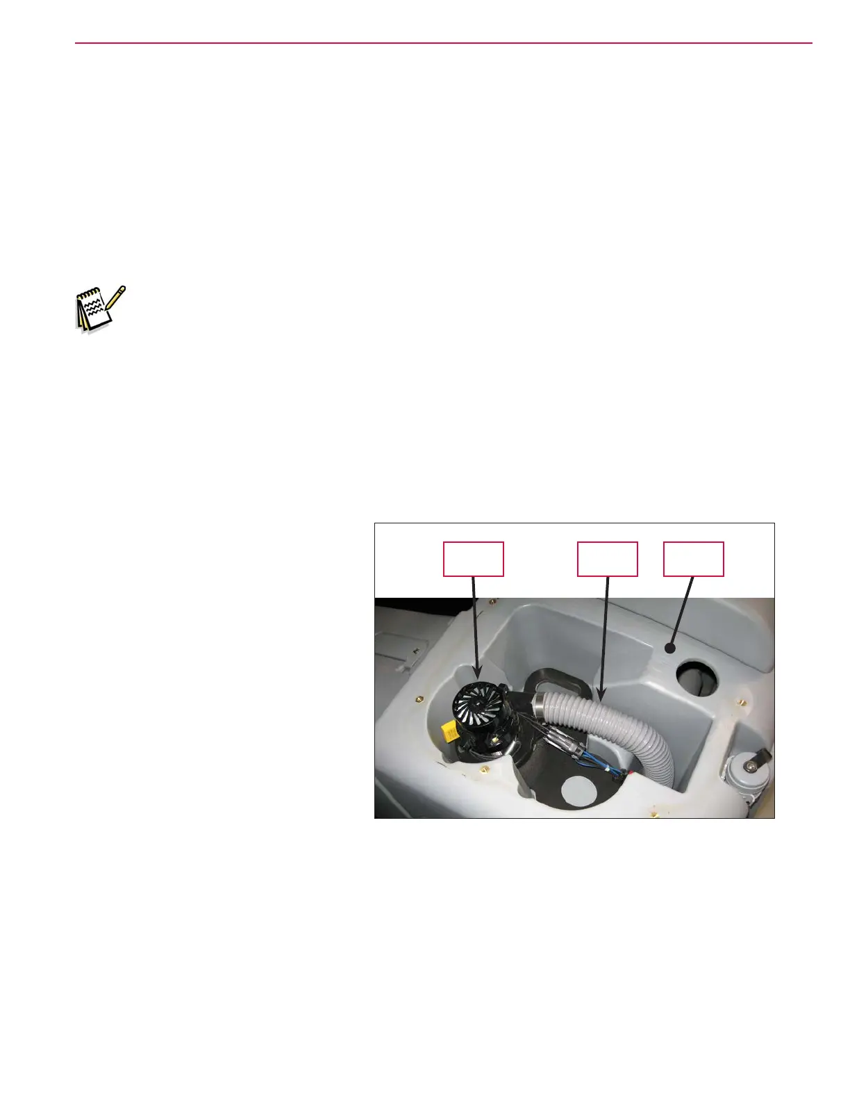
Component Locations
Vacuum Motor and Vacuum Hose
The Vacuum Motor sits in a cavity in the
Recovery Tank. To access the Vacuum
Motor
, remove the ve Phillips screws and
washers holding the top cover assembly
on the recovery tank and remove the top
cover assembly.
Note that there is room in the
Recovery Tank for an optional second
Vacuum Motor.
The Vacuum Hose is clamped to the
outlet side of the Vacuum Motor and
exhausts the airow from the Vacuum
Motor
through to the underside of the
machine.
Recovery
Tank
Vacuum
Motor
Vacuum
Hose
 Loading...