NIRStar 14.1 - User Manual
Page 115 of 124
Appendix B. How to Generate a Channel-Layout Grid for an Arbitrary Optode Array
For the example considered in Section 5.4, the optodes were arranged in a manner that corresponded in
a rather straightforward way to a simple checkerboard channel layout (Figure 16). However, the
arrangement of optodes that is best suited to a particular functional imaging study may have a more
irregular character (and a strong point of NIRScout and NIRSport systems is the flexibility they afford
users in the positioning of optodes). For concreteness, here we consider a specific example that came
from a research group interested in collecting data from a region in the back of the subject’s head,
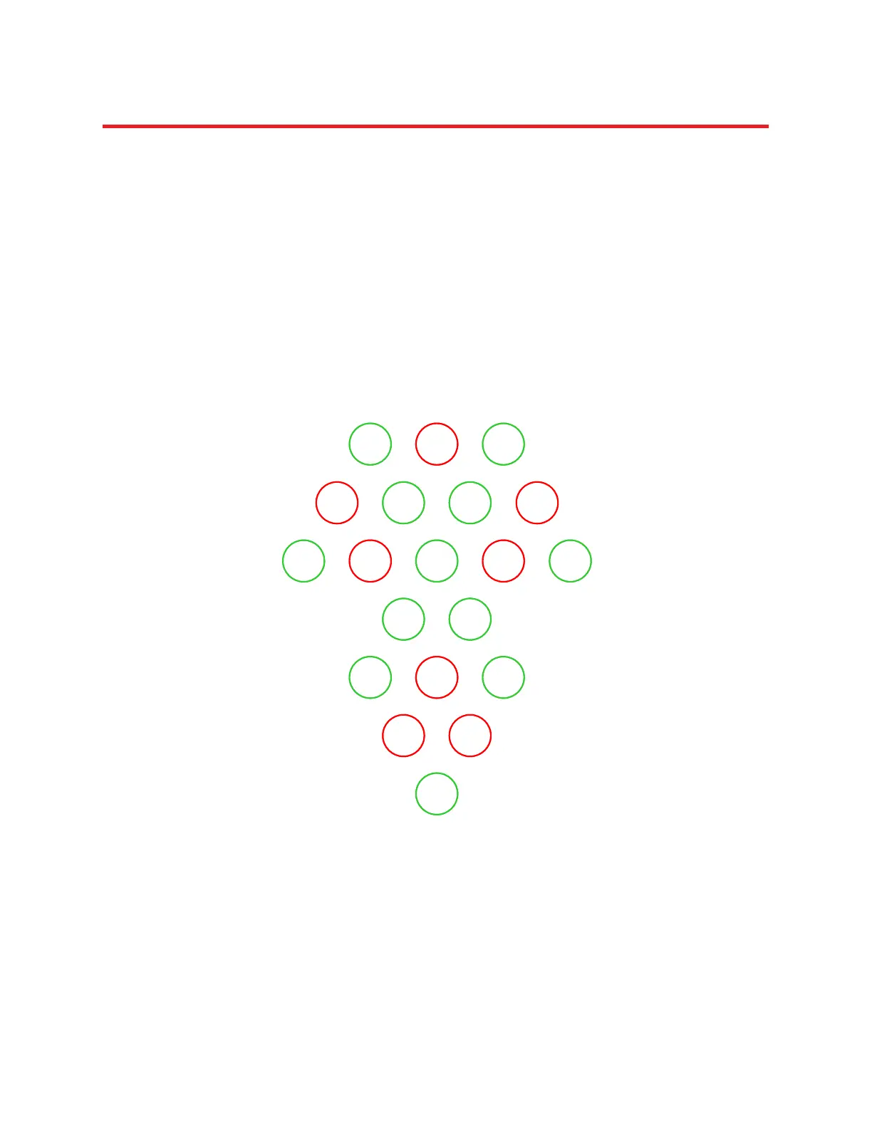
overlying the visual cortex. They used 8 sources and 12 detectors, and arranged them in the pattern
depicted in the following cartoon:
Figure 97: Example of a topographic measurement layout.
Here we present a set of steps that can be used to generate a channel layout for the array shown, and
that has worked as well for every other array tested so far.
D3 S1 D8
S3 D4 D9 S6
S4 D1 S7D6 D11
D5 D10
D7 S2 D12
S5 S8
D2
D3 S1 D8
S3 D4 D9 S6
S4 D1 S7D6 D11
D5 D10
D7 S2 D12
S5 S8
D2