NIRStar 14.1 - User Manual
Page 116 of 124
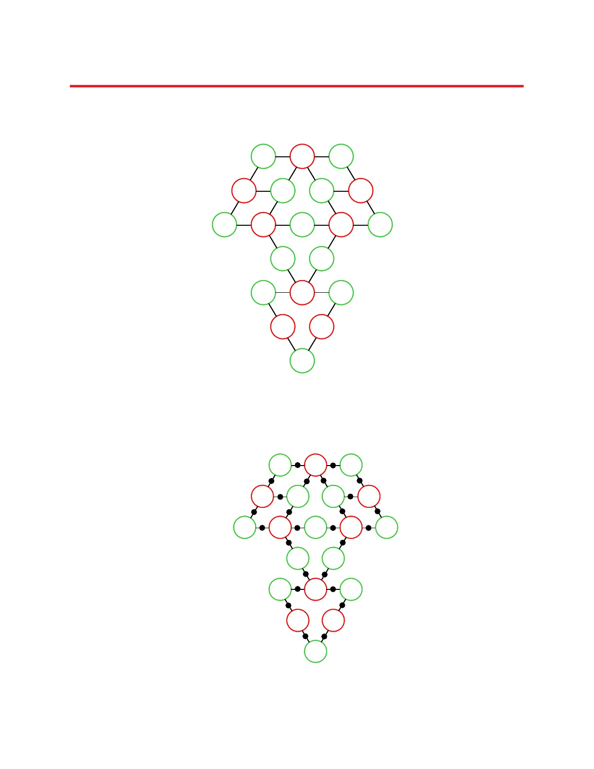
1. Draw line segments connecting all pairs of adjacent source and detector optodes (see Higher-Order
Considerations, p. 78). Each line segment represents one measurement channel:
Figure 98: Measurement channels (nearest source-detector neighbors).
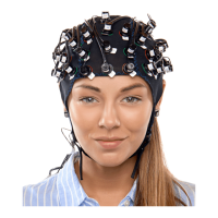
2. Place a mark in the middle of each line segment. These marks indicate the approximate locations of
the centers of the volumes of tissue that the channels are sensitive to:
Figure 99: Indication of channel positions.
D3 S1 D8
S3 D4 D9 S6
S4 D1 S7D6 D11
D5 D10
D7 S2 D12
S5 S8
D2
D3 S1 D8
S3 D4 D9 S6
S4 D1 S7D6 D11
D5 D10
D7 S2 D12
S5 S8
D2
D3 S1 D8
S3 D4 D9 S6
S4 D1 S7D6 D11
D5 D10
D7 S2 D12
S5 S8
D2
D3 S1 D8
S3 D4 D9 S6
S4 D1 S7D6 D11
D5 D10
D7 S2 D12
S5 S8
D2
D3 S1 D8
S3 D4 D9 S6
S4 D1 S7D6 D11
D5 D10
D7 S2 D12
S5 S8
D2
D3 S1 D8
S3 D4 D9 S6
S4 D1 S7D6 D11
D5 D10
D7 S2 D12
S5 S8
D2
D3 S1 D8
S3 D4 D9 S6
S4 D1 S7D6 D11
D5 D10
D7 S2 D12
S5 S8
D2