NIRStar 14.1 - User Manual
Page 118 of 124
5. Give each channel a numerical label, m-n, where m is the source number and n is the detector
number:
Figure 102: Labeling the channels.
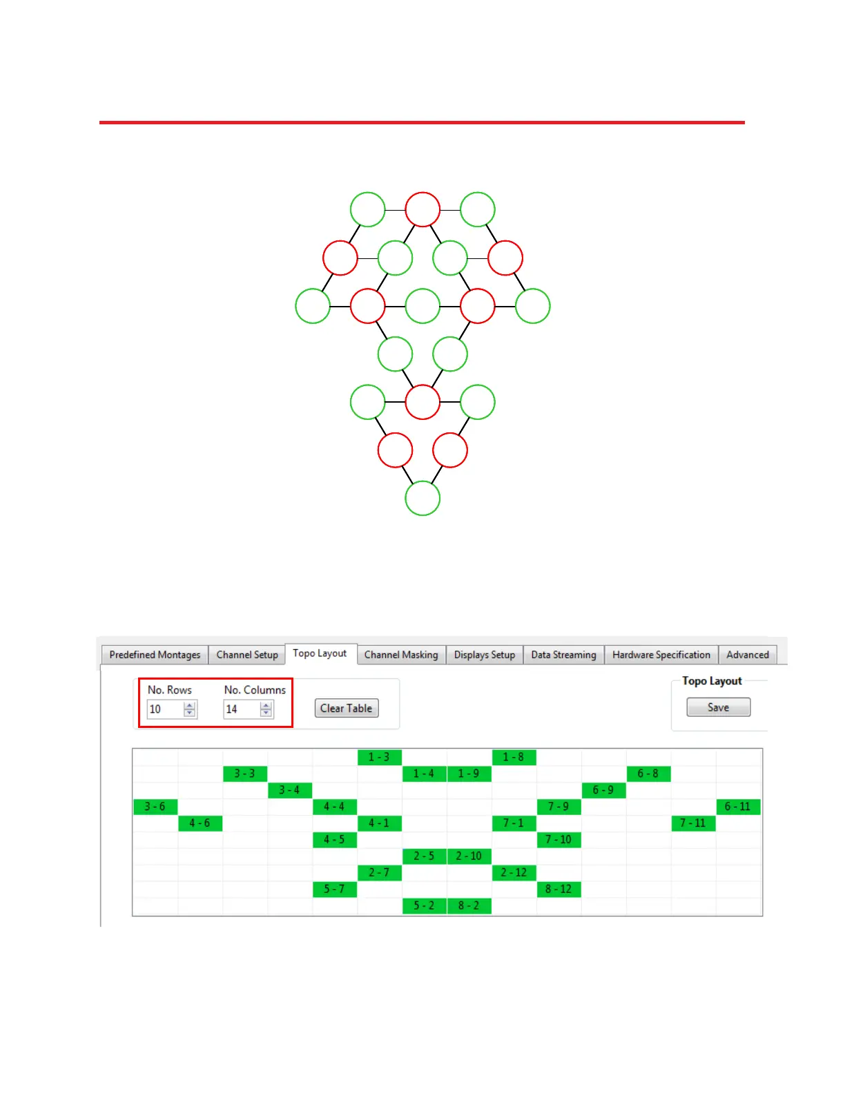
6. In the Topo Layout tab of the Configure Hardware menu, specify a layout array containing M rows and
N columns (here, M = 10 and N = 14) and fill in the channel-layout squares that correspond to the row
and column indices identified in Steps 3 and 4. Use the channel labels identified in Step 5:
Figure 103: Transfer the schematic to the layout editor
D3 S1 D8
S3 D4 D9 S6
S4 D1 S7D6 D11
D5 D10
D7 S2 D12
S5 S8
D2
1-3 1-8
3-4 6-9
4-6 4-1 7-1 7-11
2-7 2-12
3-3 1-4
1-9 6-8
3-6 4-4
7-9 6-11
4-5
7-10
2-5
2-10
5-7
8-12
5-2
8-2
D3 S1 D8
S3 D4 D9 S6
S4 D1 S7D6 D11
D5 D10
D7 S2 D12
S5 S8
D2
D3 S1 D8
S3 D4 D9 S6
S4 D1 S7D6 D11
D5 D10
D7 S2 D12
S5 S8
D2
D3 S1 D8
S3 D4 D9 S6
S4 D1 S7D6 D11
D5 D10
D7 S2 D12
S5 S8
D2
1-3 1-8
3-4 6-9
4-6 4-1 7-1 7-11
2-7 2-12
3-3 1-4
1-9 6-8
3-6 4-4
7-9 6-11
4-5
7-10
2-5
2-10
5-7
8-12
5-2
8-2
1-3 1-8
3-4 6-9
4-6 4-1 7-1 7-11
2-7 2-12
3-3 1-4
1-9 6-8
3-6 4-4
7-9 6-11
4-5
7-10
2-5
2-10
5-7
8-12
5-2
8-2