Revision 6
26. Continue to stack the springs, face up, face down (end with the top spring face up),
(Figure 8-68). Add
ATP,
if needed,
to
bring the level above the top
of
the Spring
Guide (Item #5).
27.
Slide the Guide Bushing (Item #6) onto the top
of
the Disc Springs (Item #11).
28.
Slide the Disc (Item #7) onto the top
of
the Guide Bushing (Item #6) and tighten.
29. Coat the Cap Nut (Item #8) with anti-seize compound. Thread the nut into the Body
(Item #1) and tighten.
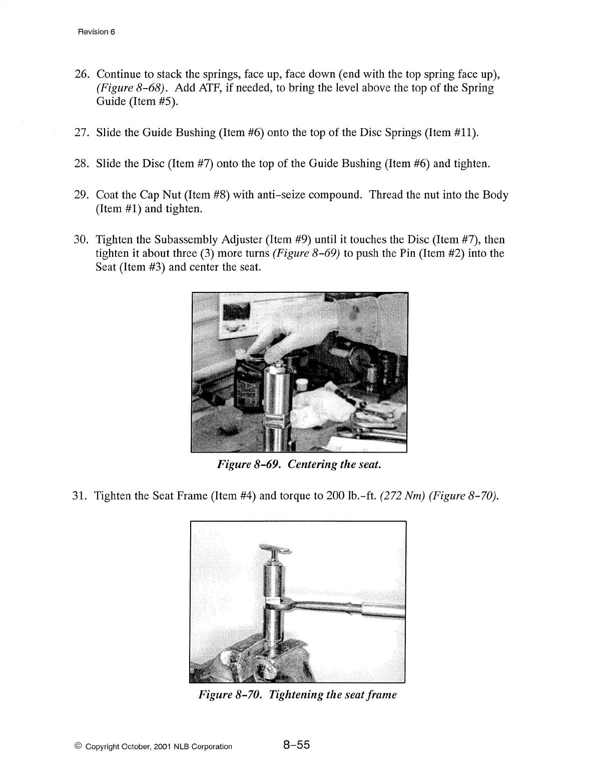
30. Tighten the Subassembly Adjuster (Item #9) until it touches the Disc (Item #7), then
tighten it about three (3) more turns
(Figure 8-69) to push the Pin (Item #2) into the
Seat (Item #3) and center the seat.
Figure 8-69. Centering the seat.
31. Tighten the Seat Frame (Item #4) and torque to 200 lb.-ft.
(272
Nm)
(Figure 8-70).
Figure 8-70. Tightening the seat frame
© Copyright October, 2001 NLB Corporation
8-55