Revision 6
B.
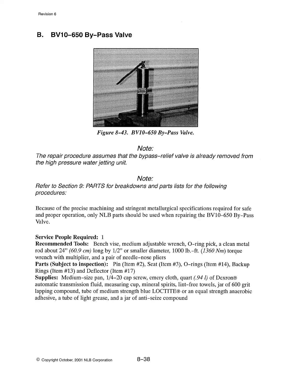
BV10-650 By-Pass Valve
Figure 8-43. BVJ0-650 By-Pass
Valve.
Note:
The repair procedure assumes that the bypass-relief valve is already removed from
the high pressure water jetting unit.
Note:
Refer to Section 9: PARTS for breakdowns and parts lists for the following
procedures:
Because
of
the precise machining and stringent metallurgical specifications required for safe
and proper operation, only NLB parts should be used when repairing the
BVl0-650
By-Pass
Valve.
Service People Required: 1
Recommended Tools: Bench vise, medium adjustable wrench,
0-ring
pick, a clean metal
rod about
24" (60.9 cm) long by 1/2" or smaller diameter, 1000 lb.-ft. (1360 Nm) torque
wrench with multiplier, and a pair of needle-nose pliers
Parts
(Subject to inspection): Pin (Item #2), Seat (Item #3),
0-rings
(Item #14), Backup
Rings (Item #13) and Deflector (Item #17)
Supplies: Medium-size pan, 1/4-20 cap screw, emery cloth, quart
(.94
l) of Dexron®
automatic transmission fluid, measuring cup, mineral spirits, lint-free towels, jar of
600 grit
lapping compound, tube
of
medium strength blue LOCTITE® or
an
equal strength anaerobic
adhesive, a tube of light grease, and a jar of anti-seize compound
© Copyright October,
2001
NLB Corporation
8-38