Revision 6
DISASSEMBLY:
Note:
For illustration purpose
only,
Rubber Bumper (Item #19)
and
Rubber Bumper (Item
#20) are shown removed.
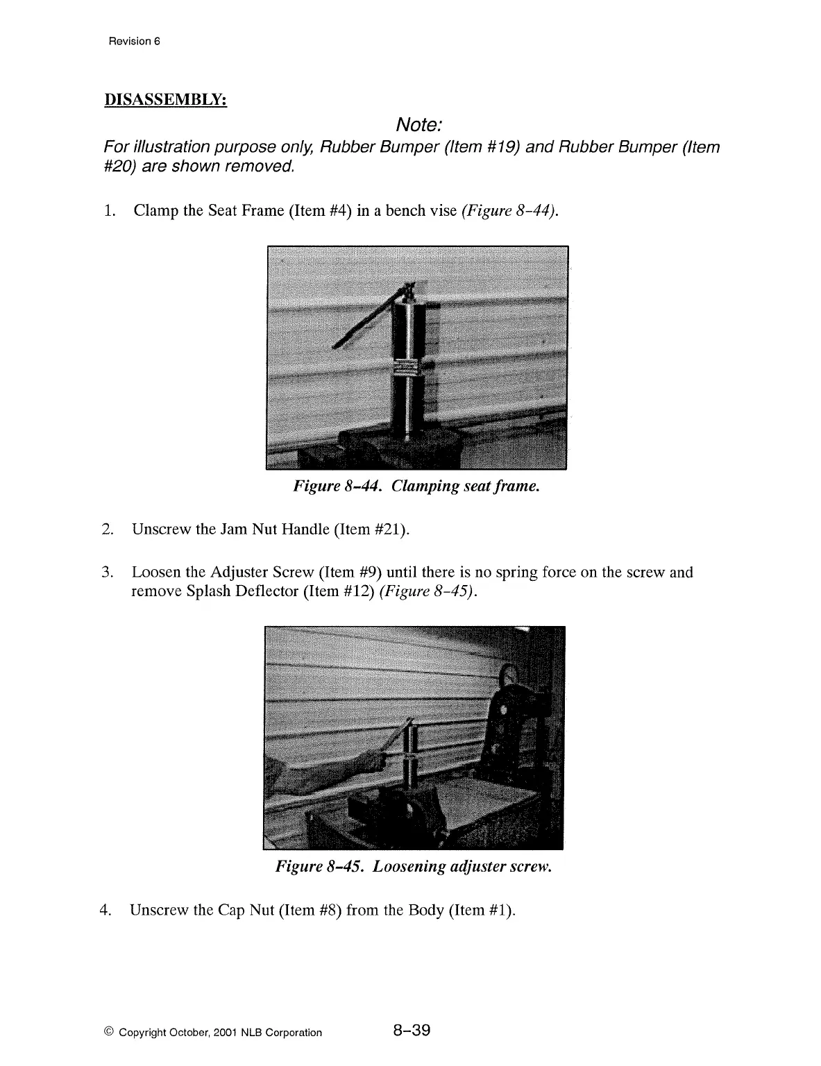
1.
Clamp the Seat Frame (Item #4) in a bench vise (Figure 8-44).
Figure 8-44. Clamping seat frame.
2.
Unscrew the Jam Nut Handle (Item #21 ).
3.
Loosen the Adjuster Screw (Item #9) until there is no spring force on the screw and
remove
Splash Deflector (Item #12) (Figure 8-45).
Figure 8-45. Loosening adjuster
screw.
4.
Unscrew the Cap Nut (Item #8) from the Body (Item #1 ).
© Copyright October,
2001
NLB Corporation
8-39