Revision
11
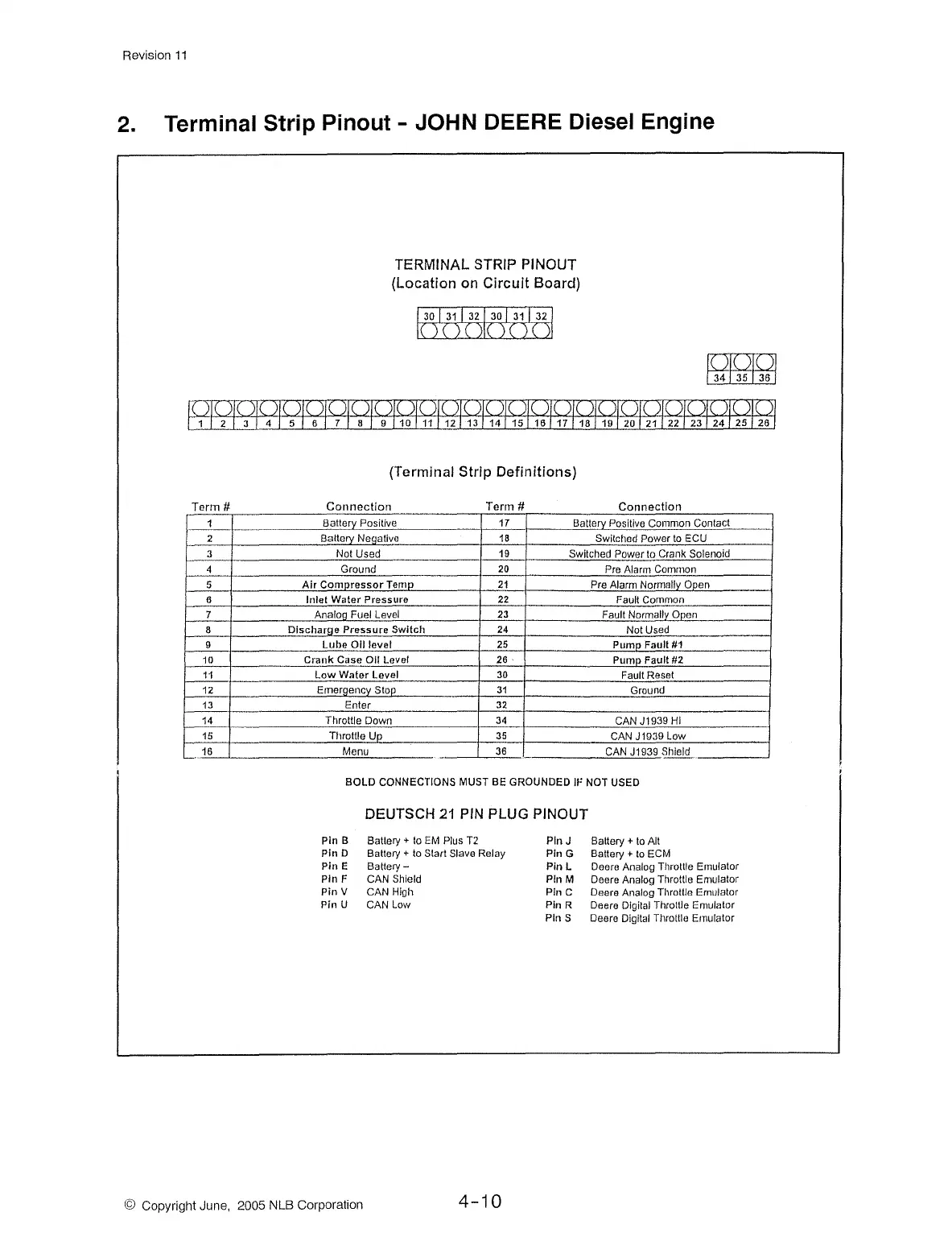
2.
Terminal Strip Pinout - JOHN DEERE Diesel Engine
Terrn #
1
2
3
4
5
6
7
8
9
10
11
12
13
14
15
16
-·
TERMINAL STRIP PINOUT
{Location on
Circuit
Board)
j 30 I
31
I 32 J 30 I 31 I
32
j
( ) ( ) ( )\( ) ( ) ( )
(Terminal Strip Definitions)
Connection Terrn #
Connection
Batterv Positive 17 Batterv Positive Common Contact
Batterv
Neaative 18
Switched Power
to
ECU
Not Used 19
Switched Power to Crank Solenoid
Ground
20
Pre Alarm Common
Air
Compressor
Ternp
21
Pre Alarm Normally Open
Inlet
Water
Pressure
22
Fault Common
Analoa Fuel Level
23
Fault Normallv Ooen
Dlscharne
Pressure
Switch
24
Not Used
Lube
Oil
level 25
Pump
Fault #1
Crank
Case
011
Level 26
Pump Fault
#2
Low
Water
Level 30
Fault Reset
Emeraencv
Stop
31
Ground
Enter
32
Throttle Down 34
CAN
J1939
Hi
Tl1rottle Uo
35
CAN
J1939
Low
Menu
36
CAN
J1939
Sl1leld
-
BOLD
CONNECTIONS MUST BE GROUNDED
Ir
NOT USED
Pin B
Pin
D
Pin
E
Pin
F
Pin
V
Pin
U
DEUTSCH
21
PIN
PLUG PINOUT
Battery+ lo
EM
Plus
T2
Battery + to Start Slave Relay
Battery-
CAN Shield
CAN High
CAN Low
PlnJ
Pin G
Pin L
Pin M
Pin C
Pin R
Pin S
Battery +
to
Alt
Battery +
to
ECM
Deere Analog
Throttle Emulator
Deere Analog Throttle Emulator
Deere Analog Throttle Emulator
Deere Digital Throttle Emulator
Deere Digital Throttle Emulator
© Copyright June, 2005 NLB Corporation
4-10