Revision 6
F.
NSP 3000 Rupture Disc Valve Assembly
Note:
Refer to Section 9: PARTS for breakdowns
and
parts lists for the following
procedures:
Service People Required: 1
Recommended Tools: 1-1/4" and 13/16" combination wrenches, small screwdriver or 1/8"
(3.2 mm) rod, a small adjustable wrench
Parts:
New Rupture Disc (Item #3)
Supplies:
Anti-seize compound
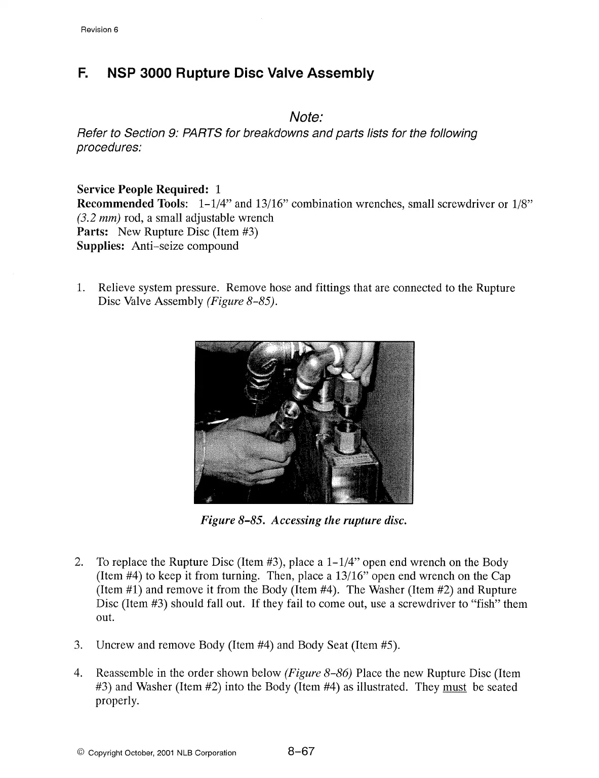
1.
Relieve system pressure. Remove hose and fittings that are connected to the Rupture
Disc Valve Assembly (Figure 8-85).
Figure 8-85. Accessing the rupture disc.
2.
To
replace the Rupture Disc (Item #3), place a 1-1/4" open end wrench on the Body
(Item
#4) to keep it from turning. Then, place a 13/16" open end wrench on the Cap
(Item #1) and remove it from the Body (Item #4). The Washer (Item #2) and Rupture
Disc (Item
#3) should fall out.
If
they fail to come out, use a screwdriver to "fish" them
out.
3.
Uncrew and remove Body (Item #4) and Body Seat (Item #5).
4.
Reassemble in the order shown below (Figure 8-86) Place the new Rupture Disc (Item
#3) and Washer (Item #2) into the Body (Item #4) as illustrated. They must be seated
properly.
© Copyright October, 2001 NLB Corporation
8-67