Revision 2
b.
Suction
and
Discharge Manifolds and Valve Assemblies
Service People Required: 2
Recommended Tools: Assorted pipe wrenches,
Special Tool (ST 1-5/8" Socket Adapter)
Special Tool (ST 1-3/4" Socket Adapter), 3/4" socket & ratchet wrench, slotted screwdriver,
0-ring
pick, 3/4" drive torque wrench 200-600 lb.ft. (270-810 Nm), two (2) each 1/2"-13
eye bolts, and a chain hoist
Supplies: Clean lint-free rags and a tube
of
valve grinding compound
Parts
(Subject to inspection): View upon disassembly of unit
Note:
Refer to Section 9: PARTS for breakdowns and parts lists for the following
procedures:
WARNING:
DISCONNECT THE BATTERY NEGATIVE(-) CABLE FIRST. BLEED DOWN ALL
HIGH
PRESSURE LINES.
PUT
A "DO
NOT
OPERATE"
TAG
ON
THE
CONTROLS. FAILURE TO
DO
SO
MAY
RESULT IN DAMAGE
TO
EQUIPMENT
AND/OR PERSONAL INJURY.
Removal
of
Suction
and
Discharge Manifolds:
1.
Remove sufficient piping or accessories from the manifold so that it can be completely
separated from the pump and placed on a clean workbench.
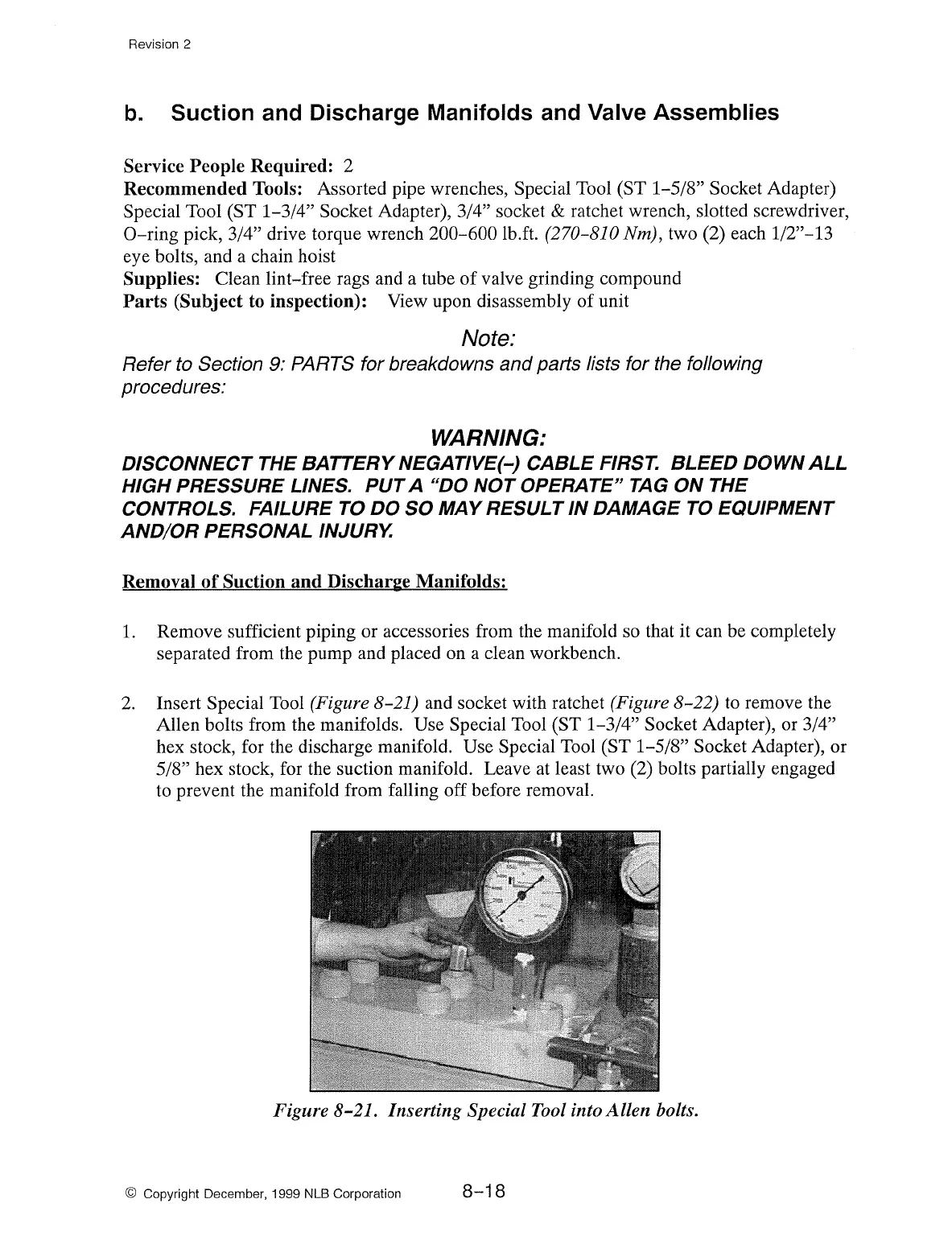
2.
Insert Special Tool (Figure 8-21) and socket with ratchet (Figure 8-22)
to
remove the
Allen bolts from the manifolds.
Use Special Tool (ST 1-3/4" Socket Adapter), or 3/4"
hex stock, for the discharge manifold. Use Special Tool (ST 1-5/8" Socket Adapter), or
5/8" hex stock, for the suction manifold. Leave
at
least two (2) bolts partially engaged
to
prevent the manifold from falling off before removal.
Figure 8-21. Inserting Special Tool into
Allen
bolts.
© Copyright December, 1999 NLB Corporation
8-1
8