7210 SAS-D CHASSIS INSTALLATION GUIDE Installing the Chassis
Issue: 08 3HE 10087 AAAA TQZZA Edition 01 37
To ensure that the equipment is connected to earth ground, use the following
instructions to prepare the ground wire and make the connection. The ground wire is
not provided. The length of the ground wire depends on the location of the switch and
proximity to the proper grounding facilities.
Tools and hardware required:
• wire stripper
• wire cutter
• crimping tool
• M4 ring lug
• slot M4 x 10 mm screw
• screwdriver for slot screws
• minimum #8 AWG wire (green, or green/yellow)
Step 1. If mounting the switch in a rack, ensure that the rack on which the switch is
to be mounted is properly grounded.
Step 2. Run a single length of #8 AWG wire (minimum) from the ground point
(building ground, equipment ground bus, or rack ground) to the switch.
Step 3. Using a wire-stripping tool, strip the insulation from the end of the wire
according to local safety codes and crimp the ring lug to the wire.
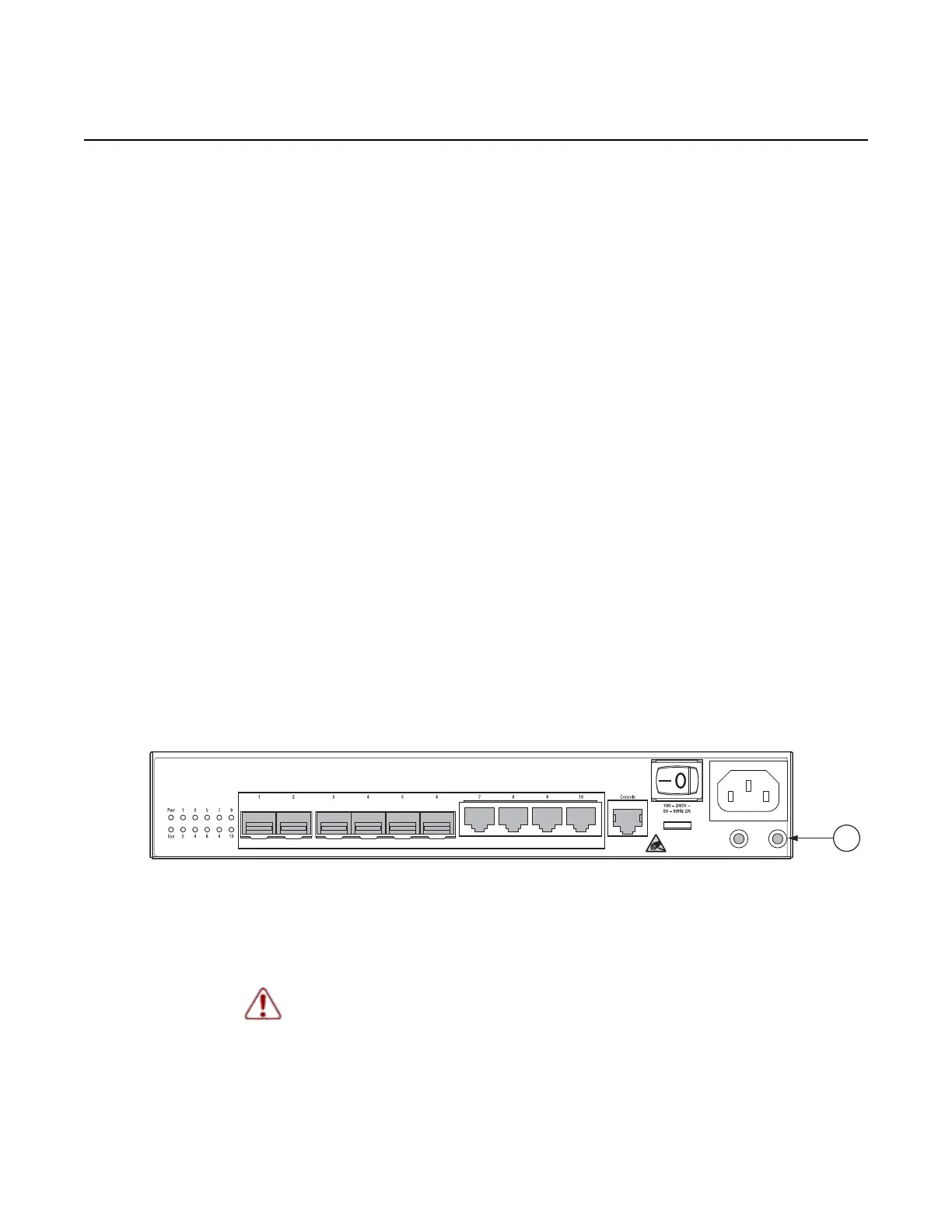
Step 4. Insert the M4 screw through the ring lug and into the switch grounding
socket (item 1 in Figure 15). Tighten the screw to secure the lug.
Figure 15 Switch Grounding Socket
Step 5. Form a service loop with the extra wire and secure it to a convenient place
(for example, a rack upright).
Warning: For radio site equipment, avoid using loops or 90-degree bends on
ground connections, as these will impede the path to ground during lightning strikes
or other power impulse events.

 Loading...